CONSUMER SERVICES TECHNICAL EDUCATION GROUP PRESENTS L-78 FRONT-LOADING AUTOMATIC WASHER MODELS: WFW8300SW, WFW8500SW, WFW8500SR JOB AID Part No.
FORWARD This Whirlpool Job Aid, “Duet Sport™ Front-Loading Automatic Washer” (Part No. 8178558), provides the technician with information on the installation, operation, and service of the Duet Sport™ Front-Loading Automatic Washer. For specific information on the model being serviced, refer to the “Use and Care Guide,” or “Tech Sheet” provided with the washer. The Wiring Diagram used in this Job Aid is typical and should be used for training purposes only.
TABLE OF CONTENTS Page GENERAL . . . . . . . . . . . . . . . . . . . . . . . . . . . . . . . . . . . . . . . . . . . . . . . . . . . . . . . . . . . . . . Washer Safety . . . . . . . . . . . . . . . . . . . . . . . . . . . . . . . . . . . . . . . . . . . . . . . . . . . . . . . . . . Model & Serial Number Designations . . . . . . . . . . . . . . . . . . . . . . . . . . . . . . . . . . . . . . . . Model & Serial Number Label And Tech Sheet Locations . . . . . . . . . . . . . . . . . . . . . . . . .
Page DIAGNOSTICS & TROUBLESHOOTING . . . . . . . . . . . . . . . . . . . . . . . . . . . . . . . . . . . . . . 6-1 Diagnostics . . . . . . . . . . . . . . . . . . . . . . . . . . . . . . . . . . . . . . . . . . . . . . . . . . . . . . . . . . . . 6-1 Diagnostic Guide . . . . . . . . . . . . . . . . . . . . . . . . . . . . . . . . . . . . . . . . . . . . . . . . . . . . . . 6-1 Failure/Error Display Codes . . . . . . . . . . . . . . . . . . . . . . . . . . . . . . . . . . . . . . . . . . . . .
GENERAL WASHER SAFETY Your safety and the safety of others is very important. We have provided many important safety messages in this Job Aid and on the appliance. Always read and obey all safety messages. This is the safety alert symbol. This symbol alerts you to potential hazards that can kill or hurt you and others. All safety messages will follow the safety alert symbol and either the word “DANGER” or “WARNING.
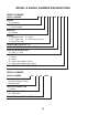
MODEL & SERIAL NUMBER DESIGNATIONS MODEL NUMBER MODEL NUMBER W F W 8 BRAND W = Whirlpool ACCESS F = Front Loading PRODUCT W = Washer SERIES 5 = Whirlpool Leap 6 = Oasis 7 = 24˝ Front Load 8 = Mid Line Front Load 9 = Duet Front Load PRICE POINT LEVELS (1 - 9) TRADE PARTNER ID (00 = BRANDED) YEAR OF INTRODUCTION S = 2006, T = 2007 COLOR CODE T = Biscuit Q = White W = White With Metallic Accent R = White With Metallic (Sport Only) ENGINEERING CHANGE (NUMERIC) SERIAL NUMBER SERIAL NUMBER HL T 35 10901
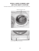
MODEL & SERIAL NUMBER LABEL AND TECH SHEET LOCATIONS The Model & Serial Number Label and Tech Sheet locations are shown below.
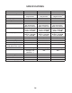
SPECIFICATIONS Model Number WFW8300SW WFW8500SW WFW8500SR Model Description Front Load Washer Front Load Washer Front Load Washer Color White with Gray Accents White with Gray Accents White with Sterling Bright Accents Capacity (Cu.Ft. IEC) 3.3 3.6 3.
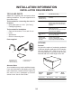
INSTALLATION INFORMATION INSTALLATION REQUIREMENTS TOOLS AND PARTS Gather the required tools and parts before starting installation. The parts supplied are in the washer drum. Tools needed for connecting the water inlet hoses • Pliers (that open to 1-9/16˝ [39.5 mm]) • Flashlight (optional) Tools needed for installation • Open end wrenches 17 mm and 13 mm • Level • Wood block • Ruler or measuring tape Parts supplied If You Have You Will Need to Buy Laundry tub or standpipe taller than 96" (2.
Installation Clearances • The location must be large enough to allow the washer door to be fully opened. • Additional spacing should be considered for ease of installation and servicing. The door opens more than 90°, and it is not reversible. • Additional clearances might be required for wall, door, and floor moldings. • Additional spacing of 1˝ (2.5 cm) on all sides of the washer is recommended to reduce noise transfer. • Companion appliance spacing should also be considered.
Recommended installation spacing for recessed or closet installation, with or without a pedestal The dimensions shown are for the recommended spacing. Recessed area or closet installation 48 in 2 * (310 cm 2) 3" (7.6 cm) 3" (7.6 cm) 48" (122 cm) 48 (310 cm 2) 29¹⁄4" (80 cm) 72" (182.9 cm) 3" (7.6 cm) 4" (10.2 cm) A B A. Side view - closet or confined area B. Closet door with vents 5 ¹⁄4 "** (13.3 cm) A 1" (2.5 cm) 29¹⁄4" (80 cm) 1" (2.5 cm) 27" (68.6 cm) 1"*** (2.
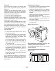
DRAIN SYSTEM Laundry tub drain system (view A) The laundry tub needs a minimum 20 gal. (76 L) capacity. The top of the laundry tub must be at least 30˝ (76.2 cm) above the floor. Floor drain system (view B) The floor drain system requires a siphon break that may be purchased separately. See “Tools and Parts.” The siphon break must be a minimum of 28˝ (71 cm) from the bottom of the washer. Additional hoses might be needed.
ELECTRICAL REQUIREMENTS GROUNDING INSTRUCTIONS For a grounded, cord-connected washer: This washer must be grounded. In the event of a malfunction or breakdown, grounding will reduce the risk of electrical shock by providing a path of least resistance for electric current. This washer is equipped with a cord having an equipment-grounding conductor and a grounding plug.
INSTALLATION INSTRUCTIONS REMOVE TRANSPORT SYSTEM 4. NOTE: If the washer is to be transported at a later date, call your local service center. To avoid suspension and structural damage, your machine must be properly set up for relocation by a certified technician. Excessive Weight Hazard Use two or more people to move and install washer. Failure to do so can result in back or other injury. CONNECT THE INLET HOSES Insert new flat washers (supplied) into each end of the inlet hoses.
Clear the water lines 1. Run water through both faucets and inlet hoses, into a laundry tub, drainpipe or bucket, to get rid of particles in the water lines that might clog the inlet valve screens. 2. Check the temperature of the water to make sure that the hot water hose is connected to the hot water faucet and that the cold water hose is connected to the cold water faucet. NOTE: Replace inlet hoses after 5 years of use to reduce the risk of hose failure.
LEVEL THE WASHER To keep drain water from going back into the washer: • Do not straighten the drain hose, and do not force excess drain hose into standpipe. Hose should be secure, but loose enough to provide a gap for air. • Do not lay excess hose on the bottom of the laundry tub. One foot has been installed at a different height on your new washer. The other three feet were preset at the factory. Properly leveling your washer will minimize excessive noise and vibration. 1.
COMPLETE INSTALLATION 1. 2. 3. 4. 5. 6. Check the electrical requirements. Be sure that you have the correct electrical supply and the recommended grounding method. See “Electrical Requirements.” Check to be sure all parts are now installed. If there is an extra part, go back through the steps to see which step was skipped. Check that you have all of your tools. Dispose of or recycle all packaging materials. Check that the water faucets are on. Check for leaks around faucets and inlet hoses.
— NOTES — 2-10
PRODUCT OPERATION FEATURES AND BENEFITS The front-loading high efficiency washer was designed to conserve resources and lower your water and energy bills. The washer is designed to determine and then provide the amount of water needed for the best performance. The time of operation may be greater for this new system than for a conventional washer.
SMART DISPENSERS added after the enzymes have had a chance to do their cleaning. The fabric softener is dispensed in the rinse cycle or in the EXTRA RINSE, if selected. The Detergent Advantage System Dispenser tray is easily removed for cleaning. The three compartments in the dispenser allow loading of all laundry additives before the washer is started. The additives will be dispensed into the wash at the optimal time for high performance cleaning.
WASHER USE MODEL WFW8300S MODEL WFW8500S STARTING THE WASHER WARNING: To reduce the risk of fire, electric shock, or injury to persons, read the IMPORTANT SAFETY INSTRUCTIONS before operating this appliance. The following is a guide to using the washer. Please refer to specific sections of this manual for more detailed information. Do not store laundry products on the top surface of this washer. Vibration is normal during operation.
USING THE PROPER DETERGENT Use only High Efficiency detergents. The package for this type of detergent will be marked “HE” or “High Efficiency.” This wash system, along with less water, will create too much sudsing with a regular non-HE detergent. Using regular detergent will likely result in washer errors, longer cycle times, and reduced rinsing performance. It may also result in component failures and noticeable mold or mildew.
8. • When the wash cycle is complete, the CYCLE COMPLETE status light illuminates, the door unlocks, and the wash load can be removed from the washer. The washer powers down automatically 5 minutes after the cycle is complete and the CYCLE COMPLETE light goes off. To power down the washer manually after the wash cycle is complete, select PAUSE/CANCEL once. To begin the wash cycle later Select DELAY WASH until the desired delay time (in hours) is displayed. Select START.
CHANGING CYCLES AND OPTIONS • Liquid detergent: Measure the amount of liquid detergent with the measurement device which comes with the detergent. Add no more than the manufacturer’s recommended amount. The liquid detergent flows immediately into the washer. • Powdered detergent: Measure the amount of powdered detergent with the measurement device which comes with the detergent. Add no more than the manufacturer’s recommended amount. NOTE: Overfilling could cause an oversudsing condition.
Adding items You can add items to the washer after the wash cycle has started, if the ADD A GARMENT status light is illuminated. All cycles have this feature except Rinse/Spin and Drain/Spin. To add items 1. Select PAUSE/CANCEL. The washer door unlocks, and items can be added. 2. To continue the cycle, close the door and select and hold START (for approximately 1 second). 3. To unlock the door after the Add a Garment period, press PAUSE/CANCEL twice. This will cancel the Wash Cycle.
Preset Cycle Settings Each cycle has a preset Cycle Time, WASH/ RINSE TEMP, and SPIN SPEED. The preset settings provide the recommended fabric care for the selected cycle. See chart. Cycle Estimated Time* Wash Temp Whitest Whites This cycle is especially designed for cleaning loads of soiled white fabrics with the addition of bleach. Hot washing temperatures assure optimal bleach activity. An additional rinse provides optimal rinse performance to avoid chlorine residues on your laundry.
NORMAL SOUNDS Clean Washer Use the Clean Washer cycle once a month to keep the inside of your washer fresh and clean. This cycle uses a higher water level in combination with liquid chlorine bleach to thoroughly clean the inside of your washing machine. See “Cleaning The Washer.” As with any new product, you will hear sounds that you are not accustomed to. You may hear various sounds when the door is locked or unlocked, and during the washing, rinsing, or spinning process.
Extra Rinse Temperature Guide An extra rinse can be used to aid in the removal of detergent or bleach residue from garments. This option provides an additional rinse with the same water temperature as in the normal rinse. It is a preset setting for the Whitest Whites cycle. You may select or deselect by pressing EXTRA RINSE. Prewash Use this option for loads of heavily soiled garments that need pretreatment. • Add detergent to the Main Wash Compartment of the dispenser drawer.
LAUNDRY GUIDE Refer to the chart below for suggested load types and their corresponding cycles. Listed to the right are the options available to each of these washer cycles. CYCLE SUGGESTED LOAD TYPE AVAILABLE OPTIONS Delay Wash Sanitary Heavily soiled underwear, towels, work cloths, diapers, etc. Whitest Whites Soiled white fabrics Heavy Duty Heavily soiled underwear, towels, shirts, etc., made of cotton Normal/Casual Normally soiled blouses, shirts, overalls, etc.
WASHER CARE CLEANING THE WASHER Cleaning the Door Seal/Bellow 1. Open the washer door and remove any clothing or items from the washer. 2. Inspect the gray colored seal/bellow between the door opening and the basket for stained areas. Pull back the seal/ bellow to inspect all areas under the seal/bellow and to check for foreign objects. A A. Seal/Bellow If stained areas are found, wipe down these areas of the seal/bellow, using the procedure that follows.
8. 9. Once the cycle has begun, allow the cycle to complete. After the cycle is complete, leave the door open, slightly, to allow for better ventilation and drying of washer interior. Always do the following to maintain washer freshness • Use only HE High Efficiency detergent. • Leave the door slightly open after each cycle to allow for better ventilation and drying of washer interior. • Repeat the cleaning procedure monthly, using 2/3 cup (160 mL) of liquid chlorine bleach.
Electrical Shock Hazard Plug into a grounded 3 prong outlet. Do not remove ground prong. Do not use an adapter. Do not use an extension cord. Failure to follow these instructions can result in death, fire, or electrical shock. 4. 5. Plug in washer or reconnect power. Run the washer through the Normal/Casual cycle. Use only HE High Efficiency detergent. Use 1/2 the manufacturer’s recommended amount for a medium sized load. To transport the washer: 1.
TROUBLESHOOTING WASHER & COMPONENTS ERROR CODES When all cycle indicator lights are blinking, see which status light is also illuminated and then check the list below for potential problem and troubleshooting checks. An error code may be shown in the Estimated Time Remaining display (on some models).
LEAKING • Was the door opened during “Add a garment”? Water can drip off the inside of the door, when the door is opened after the start of a cycle. • Is HE detergent being used? The non-High Efficiency detergents can cause oversudsing that can leak from the rear of the washer. • Are the fill hoses tight? • Are the fill hose gaskets properly seated? Check both ends of each hose. See “Connect the Inlet Hoses.
WASHER OPERATION • Are the shipping bolts removed? All four shipping bolts must be removed for proper operation of the washer. WASHER WON’T RUN, FILL, RINSE, OR TUMBLE; WASHER STOPS • Has a cycle been selected, but START has not been selected and held for 1 second? Press and hold START, for 1 second. • Was the door open after completion of last cycle? The door must be opened and closed again to start a new cycle.
CLOTHES CARE WASH / RINSE TEMPERATURE • Are the hot and cold water inlet hoses reversed? See “Connect the Inlet Hoses.” • Are you washing many loads? As your frequency of loads washed increases, the water temperature may decrease for hot and warm temperatures. This is normal. CYCLE TIME CHANGES/CYCLE TOO LONG • Estimated cycle time? The cycle times vary automatically based on your water pressure, water temperature, detergent, and clothes load.
• Are you using a low speed wash cycle? Powdered detergents may not dissolve well in a slow-speed cycle. For best results, use liquid detergent for slow-speed cycles such as Delicate. LOAD IS WRINKLED, TWISTED, TANGLED • Did you unload the washer promptly? Unload the washer as soon as it stops. • Did you unload the washer promptly? To avoid dye transfer, unload the washer as soon as it stops.
— NOTES — 3-20
COMPONENT ACCESS This section instructs you on how to service each component inside the Duet Sport™ Front-Loading Automatic Washer. The components and their locations are shown below.
REMOVING THE CONSOLE AND THE TOUCHPAD/LED ASSEMBLY 5. UI8 Electrical Shock Hazard Disconnect power before servicing. Replace all parts and panels before operating. Failure to do so can result in death or electrical shock. 1. 2. 3. 4. To remove the console: a) Pull out and disconnect cable connector UI8 from the central control unit. b) Remove the cable wires from the two central control unit clips. Central Control Unit Unplug washer or disconnect power. Turn off the water supply to the washer.
d) Remove the two screws at the recessed hole and bottom of the console. 6. To remove the touchpad/LED assembly: a) Pull the selector knob off the switch shaft. b) Press the seven console locking tabs, and unsnap the touchpad/LED assembly, then lift the assembly from the console and remove it. Pull Off Selector Knob Console Screws e) Lift the top edge of the console and unhook it from the holder clips.
REMOVING THE CENTRAL CONTROL UNIT Central Control Unit Connectors (12) Electrical Shock Hazard Disconnect power before servicing. Replace all parts and panels before operating. Failure to do so can result in death or electrical shock. Wire Clamps 1. 2. 3. Unplug washer or disconnect power. Turn off the water supply to the washer. Remove the top cover from the washer (see page 4-2 for the procedure). 6.
Make sure that you seat the connectors firmly onto the circuit board, and that they lock securely into place. REASSEMBLY NOTE: The photo shows the connector callouts for the central control unit.
REMOVING THE WATER INLET VALVE Lift Locking Tab Pull Connector Out Electrical Shock Hazard Disconnect power before servicing. Replace all parts and panels before operating. Failure to do so can result in death or electrical shock. 1. 2. 3. 4. Cold Water (Stripe) Unplug washer or disconnect power. Turn off the water supply to the washer. Remove the water hoses from the hot and cold water inlet valve. Remove the top cover (see page 4-2 for the procedure).
REMOVING THE PRESSURE SWITCH 4. 5. Electrical Shock Hazard Disconnect power before servicing. Replace all parts and panels before operating. Failure to do so can result in death or electrical shock. 1. 2. 3. Press and release the two wire connector locking arms and pull the connector off the pressure switch. Pull the pressure hose off the pressure switch fitting. Wire Connector Pressure Switch Unplug washer or disconnect power. Turn off the water supply to the washer.
REMOVING THE LINE FILTER & POWER SUPPLY CORD c) Disconnect the three wire connectors from the line filter. NOTE: Press and release the locking arm on the 2-wire connector to disconnect it from the filter. Line Filter Wire Connectors Electrical Shock Hazard Disconnect power before servicing. Replace all parts and panels before operating. Failure to do so can result in death or electrical shock. 1. 2. 3. Unplug washer or disconnect power. Turn off the water supply to the washer.
c) Pull the washer away from the wall far enough to access the power supply cord on the rear panel. d) Use a pair of pliers and turn the strain relief on the power supply cord 90° in either direction. Align the strain relief key with the slot in the rear panel, and remove the cord from the washer.
REMOVING THE DETERGENT DISPENSER ASSEMBLY 7. 8. Remove the left hex-head screw from the support bracket. Loosen the clamp and remove the water supply tube from the detergent dispenser. Left Support Bracket Screw Electrical Shock Hazard Disconnect power before servicing. Replace all parts and panels before operating. Failure to do so can result in death or electrical shock. 1. 2. 3. Water Supply Tube Unplug washer or disconnect power. Turn off the water supply to the washer.
10. Remove the three hex-head screws from the lower front access panel, then lower the panel, and remove it. 13. Pull the bellows off the lip of the front panel, and push the bellows inside the front panel. 14. Remove the two T-20 Torx screws from the door switch assembly. Lower Front Access Panel Screws Door Switch Assembly Screws 11. Open the washer door. Bellows Pull Bellows Off Lip Of Panel 15. Close the washer door. 16.
17. Loosen the clamp from the main water feed tube and remove the tube from the detergent dispenser. REASSEMBLY NOTE: When you reconnect the water feed tube, align the arrow on the tube with the line on the detergent dispenser. 18. Pull back and unhook the tab on the left side of the detergent dispenser from the cabinet side panel slot, then lift the dispenser out of the washer.
REMOVING THE DETERGENT DISPENSER MOTOR 4. 5. Electrical Shock Hazard Disconnect power before servicing. Replace all parts and panels before operating. Failure to do so can result in death or electrical shock. 1. 2. 3. 6. Lift the locking tabs and remove the two wire connectors from the detergent dispenser motor terminals. NOTE: When you reconnect the wire connectors, make sure to position the connector with the blue stripe on top. Pry up on the cam actuator and unsnap it from the motor shaft.
REMOVING THE DOOR SWITCH ASSEMBLY AND THE BELLOWS 6. Electrical Shock Hazard Disconnect power before servicing. Replace all parts and panels before operating. Using a small screwdriver or a pair of long-nosed pliers, pull the tension spring on the retaining wire out from around the front of the bellows, and remove the wire. Retaining Wire Tension Spring Failure to do so can result in death or electrical shock. 1. 2. 3. 4. 5. Unplug washer or disconnect power. Turn off the water supply to the washer.
c) Pull the door switch assembly out and turn it over so that you can access the connectors. d) Unlock the tabs and disconnect the three wire connectors from the door switch terminals, then remove the assembly. Bellows Retaining Clamp Screw 3 Door Switch Assembly Connectors d) Remove the bellows retaining clamp from around the bellows. Remove Bellows Retaining Clamp 8. To remove the bellows: a) Remove the two T-20 Torx screws from the door switch assembly (see the photo in step 7b).
e) Pull the bellows off the front of the tub. REASSEMBLY NOTE: When you reinstall the bellows, be sure to position the “weep holes” at the bottom, as shown below.
REMOVING THE DRAIN PUMP 5. 6. Loosen the clamp and remove the pumpto-tub hose from the drain pump. Loosen the clamp and remove the pumpto-drain hose from the drain pump. REASSEMBLY NOTE: When you reconnect the hoses, align their tab(s) with the marks on the drain pump. Electrical Shock Hazard Disconnect power before servicing. Replace all parts and panels before operating. Failure to do so can result in death or electrical shock. 1. 2. 3.
8. 9. Lift the wire cover on the drain pump, and disconnect the wire connector from the terminals. Remove the wires from the clip, and remove the drain pump from the washer. REASSEMBLY NOTE: When you reinstall the drain pump, make sure that you completely reseat the rubber pad in its chassis floor slot.
REMOVING THE ECO VALVE 5. 6. Pull the pressure hose off the air trap that is connected to the pump-to-tub/ECO valve hose. Loosen the clamps at both ends of the pump-to-tub hose, and pull the hose/ ECO valve off the tub and drain pump. Electrical Shock Hazard Disconnect power before servicing. Replace all parts and panels before operating. Failure to do so can result in death or electrical shock. 1. 2. 3. Unplug washer or disconnect power. Turn off the water supply to the washer.
REMOVING THE MOTOR CONTROL UNIT 6. Electrical Shock Hazard Disconnect power before servicing. Replace all parts and panels before operating. Failure to do so can result in death or electrical shock. 1. 2. 3. 4. 5. Pull the bottom of the rear panel out, and slide it down so the top edge is out from behind the lip of the upper panel, and remove the rear panel. Motor Control Unit Unplug washer or disconnect power. Turn off the water supply to the washer. Pull the washer away from the wall.
10. Disconnect the four wire connectors from the motor control unit and remove the unit.
REMOVING THE TEMPERATURE SENSOR & HEATER b) Loosen the 10 mm nut and pull the temperature sensor out of the heater. 10 mm Nut Pull Temperature Sensor Out Of Heater Electrical Shock Hazard Disconnect power before servicing. Replace all parts and panels before operating. Failure to do so can result in death or electrical shock. 1. 2. 3. 4. 6. Unplug washer or disconnect power. Turn off the water supply to the washer. Pull the washer away from the wall.
REMOVING THE DRIVE BELT AND MOTOR Electrical Shock Hazard Disconnect power before servicing. Replace all parts and panels before operating. Failure to do so can result in death or electrical shock. 1. 2. 3. 4. Basket Drive Pulley Unplug washer or disconnect power. Turn off the water supply to the washer. Pull the washer away from the wall. Remove the rear panel from the washer (see page 4-20 for the procedure). 6.
d) Rotate the motor down and pull it toward you so the bracket studs are out of the tub mounting holes, and remove the motor.
REMOVING AN INTERLOCK SWITCH 4. Press the two locking tabs in to release them, and slide the switch holder up and out of the chassis cutout. Locking Tabs Release Electrical Shock Hazard Disconnect power before servicing. Replace all parts and panels before operating. Failure to do so can result in death or electrical shock. 1. 2. 3. Unplug washer or disconnect power. Turn off the water supply to the washer.
6. Push out on the two locking tabs of the switch holder, rotate the switch in the direction of the arrow, and remove the switch from the holder.
REMOVING THE BASKET DRIVE PULLEY 6. Use a large screwdriver and lock the pulley, then remove the 15/16˝ nut from the drive pulley. Basket Drive Pulley Electrical Shock Hazard Disconnect power before servicing. Replace all parts and panels before operating. Failure to do so can result in death or electrical shock. 15/16˝ Nut Drive Belt 1. 2. 3. 4. 5. Unplug washer or disconnect power. Turn off the water supply to the washer. Pull the washer away from the wall.
REMOVING THE TUB & BASKET AND BAFFLE 7. Remove the eight hex-head screws from the front frame and remove the frame. Front Frame Screws Electrical Shock Hazard Disconnect power before servicing. Replace all parts and panels before operating. Failure to do so can result in death or electrical shock. 8. Remove the 1/2˝ bolts (3 each) from the front top and bottom tub weights, and remove the weights from the tub. Top Front Weight Unplug washer or disconnect power. Turn off the water supply to the washer.
10. Remove the bellows from the tub (see pages 4-14 through 4-16 for the procedure). 11. Using a shallow pan to catch the water, unscrew the filter from the drain pump, and drain the water from the pump. Drain Pump Filter 12. Loosen the clamp and remove the pumpto-tub hose from the drain pump. REASSEMBLY NOTE: When you reconnect the hose, align the tab with the arrow on the drain pump. 14. Loosen the clamp and remove the vent tube-to-tub end. Vent Tube-To-Tub 15.
18. Remove the drive motor from the tub (see page 4-23 for the procedure). 19. Remove the temperature sensor and heater from the tub (see page 4-22 for the procedure). 20. Remove the four motor control unit wiring standoffs from the tub. Squeeze in on the standoff tabs to release the standoffs. b) Using a pair of pliers, turn the top of the shock absorber 90° so that the locking tabs align with the slots in the tub, and remove the shock absorber.
b) Remove the flat nuts from the tub. Rear Half Of Tub Remove Flat Nuts c) Mark the edges of the tub clamps with a pencil to make it easier to reinstall later. d) Use a large flat-blade screwdriver and pry off the tub clamps. Front Half Of Tub Pencil Marks Tub Clamp Screwdriver Pry Clamp Off e) Use a large flat-blade screwdriver and pry the tub halves apart, then lift the rear half of the tub off the front half (see the top right photo). f) Lift the basket from the front half of the tub.
24. To replace the tub gasket, pry the gasket out of the slot, and remove it. NOTE: The tub gasket hub is molded into the rear half of the tub. If it is worn and needs to be replaced, replace the rear half of the tub. Baffle Mounting Tabs Rear Of Tub Basket Tabs Basket Hub Baffle Stops Pry Up Basket Tabs Tub Gasket 25. To replace a basket baffle (see the right column photos): a) Position the basket with the baffle to be removed on top.
COMPONENT TESTING Before testing any of the components, perform the following checks: • Control failure can be the result of corrosion on connectors. Therefore, disconnecting and reconnecting wires will be necessary throughout test procedures. • All tests/checks should be made with a VOM or DVM having a sensitivity of 20,000 ohms-per-volt DC, or greater. • Check all connections before replacing components, looking for broken or loose wires, failed terminals, or wires not pressed into connectors far enough.
Electrical Shock Hazard Disconnect power before accessing. Replace all parts and panels before operating. Failure to do so can result in death or electrical shock. To check the pressure switch at the CCU, perform the following steps. 1. Unplug washer or disconnect power. PRESSURE SWITCH Pin 1 End 2. 3. 4. Hose Inlet Refer to page 4-7 for the procedure for accessing the pressure switch. To check the pressure switch at the component terminals, perform the following steps. 1.
Electrical Shock Hazard Disconnect power before accessing. Replace all parts and panels before operating. Failure to do so can result in death or electrical shock. To check the line filter at the CCU, perform the following steps. 1. Unplug washer or disconnect power. 2. Disconnect the line filter connector IF2 (see page 4-5) from the CCU. 3. Set the ohmmeter to the R X 1 scale. 4. Touch the ohmmeter test leads to connector pins 1 and 2. The meter should indicate 0 Ω.
Electrical Shock Hazard Disconnect power before accessing. Replace all parts and panels before operating. Failure to do so can result in death or electrical shock. To check the motor at the CCU, perform the following steps. 1. Unplug washer or disconnect power. 2. Disconnect the detergent dispenser connector DI6 (see page 4-5) from the CCU. 3. Set the ohmmeter to the R X 1 scale. 4. Touch the ohmmeter test leads to the following connector pins.
Electrical Shock Hazard Disconnect power before accessing. Replace all parts and panels before operating. Failure to do so can result in death or electrical shock. DOOR SWITCH 3. 4. Set the ohmmeter to the R X 1 scale. To test the door lock/unlock solenoids, touch the ohmmeter test leads to the indicated pins on connector DL3. The meter should indicate as follows: Door Unlock Solenoid - Pins 2 & 3 = 60 Ω Door Lock Solenoid - Pins 1 & 3 = 60 Ω 5.
Electrical Shock Hazard Disconnect power before accessing. Replace all parts and panels before operating. Failure to do so can result in death or electrical shock. To check the drain pump at the CCU, perform the following steps. 1. Unplug washer or disconnect power. DRAIN PUMP 2. 3. 4. Drain Pump Connector Disconnect the drain pump connector DP2 (see page 4-5) from the CCU. Set the ohmmeter to the R X 1 scale. Touch the ohmmeter test leads to connector pins 1 and 2.
Electrical Shock Hazard Disconnect power before accessing. Replace all parts and panels before operating. Failure to do so can result in death or electrical shock. To check the temperature sensor at the CCU, perform the following steps. 1. Unplug washer or disconnect power. 2. Disconnect the temperature sensor connector TH2 (see page 4-5) from the CCU. 3. Set the ohmmeter to the R X 1K scale. 4. Touch the ohmmeter test leads to connector pins 1 and 2. The meter should indicate as shown in the chart below.
Electrical Shock Hazard Disconnect power before accessing. Replace all parts and panels before operating. Failure to do so can result in death or electrical shock. DRIVE MOTOR INTERLOCK SWITCH COM N.C. Actuator Button Pin 1 Refer to page 4-25 for the procedure for accessing an interlock switch. 1. Unplug washer or disconnect power. 2. Disconnect the wire connectors from either of the interlock switch terminals. 3. Set the ohmmeter to the R X 1 scale. 4.
DIAGNOSTICS & TROUBLESHOOTING DIAGNOSTICS DIAGNOSTIC GUIDE • A potential cause of a control not functioning is corrosion on connections. Observe connections and check for continuity with an ohmmeter. • Connectors: Look at top of connector. Check for broken or loose wires. Check for wires not pressed into connector far enough to engage metal barbs. • Resistance checks must be made with power cord unplugged from outlet, and with wiring harness or connectors disconnected.
FAILURE/ERROR DISPLAY CODES played on the washer console by all cycle lights flashing and standing status lights. Communication of failure codes will be disDISPLAY Reference Status LEDs chart, page 6-4 EXPLANATION AND RECOMMENDED PROCEDURE DISPLAY LONG DRAIN A communication error between the Central Control Unit (CCU) and the EEPROM onboard the CCU occurred. If the drain time exceeds 8 minutes the water valves turn off.
DISPLAY DISPLAY EXPLANATION AND RECOMMENDED PROCEDURE DOOR UNLOCK ERROR DRIVE MOTOR TACHOMETER ERROR If the control is unable to properly detect motor speed, the machine shuts down. If a failure occurs during high-speed spin, the door unlocks after 3 minutes. Reference Status LEDs chart, page 6-4 If the door unlock has failed 6 times. Reference Status LEDs chart, page 6-4 Possible Causes/Procedure 1. Verify the shipping system including shipping bolts, spacers and cables are removed. 2.
DISPLAY Some models do not have the display to show the failure codes. They use the status lights on the touchpad/LED. EXPLANATION AND RECOMMENDED PROCEDURE SUDS LOCK (OVERDOSE OF DETERGENT DETECTED DURING THE WASH CYCLE) If suds are detected continuously by the pressure switch during the drain or spin phases, the washer will fill 4 liters of water and during 5 minutes the unit will rest without tumbling, the water will be drained and it will try to spin or drain again.
DIAGNOSTIC TEST NOTES: This program recalls the most recent failure code first. The complete built-in service diagnostic module contains two entry modes and three modes of operation. • Press the same key to advance to the next failure code. (If the console doesn’t change then the same failure code was stored multiple times.) • If there aren’t any more failure codes all the lights on the console will turn on for 5 seconds. • Next the washer begins the Diagnostic Test.
ERROR HISTORY DISPLAY • When the press and hold entry method is used and successfully completed: The next most recent error code is to be displayed. • If there is no error code to display, or is the last one, then all lights should turn off for 0.5 seconds and then all turn on for 5 seconds. At the end of 5 seconds the lights will turn off and the control will advance to the automated test. • The control will respond by turning on all lights for 5 seconds.
MANUAL DIAGNOSTIC TEST MANUAL OVERVIEW TEST PROGRAM The washer must be empty and the control must be in the OFF state before pressing the touchpad sequence to start the test. Be sure to perform the Diagnostic Tests before replacing the system components. Starting the Test Mode Exit Condition • Close the door. • Select any one key (except PAUSE/ CANCEL) and follow the steps below, using the same key (remember the key): Press/ hold 4 sec’s. Release for 4 sec’s. Press/ hold 4 sec’s.
Manually Unlocking the Door Lock System Be sure to perform the Diagnostic Tests before replacing the system components. 1. Unplug washer or disconnect power. 2. Remove the lower kick panel. 3. Reach up along the inside of the front and locate the bottom of the door switch/lock unit. Pump Motor Continuity Test Pins 1 to 2 Results Normal = approx. 12.3 Ω Abnormal = Infinity 4. Located on the bottom of the door switch/ lock unit is a teardrop shaped tab. 5.
To reassemble CCU: WASHER CARE 1. Align the tab on top of the CCU with the notch in the cabinet. Also, align the posts on the back of the CCU with the hole in the back of the cabinet. Cleaning the door seal: 1. Open the washer door and remove any clothing or items from the washer. 2. Inspect the gray colored seal between the door opening and the basket for stained areas. Pull back the seal to inspect all areas under the seal and to check for foreign objects. 2. Slide the CCU back into place. 3.
b) If any items are detected in the washer, all cycle lights will flash and the WASH and CONTROLS LOCKED lights will remain lit. The door will unlock. Press PAUSE/CANCEL to cancel the failure code. Then repeat steps 1, 2 and 6 to start the cycle again. Begin procedure: 1. Open the washer door and remove any clothing or items from the washer. 2. Be sure the door is closed. 3. Open the dispenser drawer and immediately add 2/3 cup (160 mL) of liquid chlorine bleach to the bleach compartment.
TROUBLESHOOTING GUIDE PROBLEM WON’T POWER UP (touchpads do not respond when pressed) WON’T START CYCLE POSSIBLE CAUSE/TEST POSSIBLE CAUSE/TEST PROBLEM NOTE: Possible Cause/Tests must be performed in the sequence shown for each problem. 1. Check that the unit is plugged into a working outlet and for blown fuses. 2. Check for power going to Central Control Unit (CCU) by listening for a click in the CCU when unit is plugged in. If no click, replace CCU. 3. Unplug washer or disconnect power. 4.
POSSIBLE CAUSE/TEST PROBLEM NOTE: Possible Cause/Tests must be performed in the sequence shown for each problem. WON’T DRAIN 1. 2. 3. 4. 5. Unplug washer or disconnect power. Check wire harness connections. Check drain pump. Check drain pump motor. Check that the drain hose and drain pump filter are clear of foreign objects. 6. Plug in washer or reconnect power. 7. Verify CCU operation by running a Diagnostic Test or any cycle. MACHINE VIBRATES 1. Remove shipping system. 2. Check installation. 3.
WIRING DIAGRAMS WASHER DRIVE MOTOR N HEATING ELEMENT L DRAIN PUMP DISPENSER Motor Switch INLET VALVES DOOR LOCK/SWITCH IF DS DLS Lock Unlock VH VC MOTOR CONTROL UNIT (MCU) L2 IF2 1 DS2 1 2 DL3 1 2 2 DLS2 1 3 MS2 1 2 N1 DR1 L1 K2 2 3 4 2 3 HE2 2 1 HR2 HR1 CENTRAL CONTROL UNIT (CCU) K1 1 UI8 MI3 1 2 L2 N1 5 6 TOUCHPAD/LED ASSEMBLY 7 8 6 5 3 4 PR6 22 24 26 21 p> 2 1 11 14 1 TH2 2 p> L_0 L_wash L_overflow L_sud PRESSURE SWITCH TEMPERATURE SENSOR 7-1 DP2 1
GROUNDING SYSTEM GROUNDING SYSTEM WITHOUT HEATER S1 = GND SWITCH – FRONT S2 = GND SWITCH – REAR POWER CORD REAR CABINET S2 BELT: HIGH INSULATED MCU 1M Ω Hub MOTOR S1 FRONT GROUNDING SYSTEM WITH HEATER S1 = GND SWITCH – FRONT S2 = GND SWITCH – REAR REAR CABINET S2 MCU 1M Ω MOTOR Hub HE* S1 FRONT * Heating element not present on all models 7-2
— NOTES — 7-3
— NOTES — 7-4
PRODUCT SPECIFICATIONS AND WARRANTY INFORMATION SOURCES IN THE UNITED STATES: FOR PRODUCT SPECIFICATIONS AND WARANTY INFORMATION CALL: FOR WHIRLPOOL PRODUCTS: 1-800-253-1301 FOR KITCHENAID PRODUCTS: 1-800-422-1230 FOR ROPER PRODUCTS: 1-800-447-6737 FOR TECHNICAL ASSISTANCE WHILE AT THE CUSTOMER’S HOME CALL: THE TECHNICAL ASSISTANCE LINE: 1-800-253-2870 HAVE YOUR STORE NUMBER READY TO IDENTIFY YOU AS AN AUTHORIZED SERVICER FOR LITERATURE ORDERS: PHONE: 1-800-851-4605 FOR TECHNICAL INFORMATION AND SERVICE POI
CORPORATION