Installa on Instruc ons and Use & Care Guide Residential Electric Water Heater DO NOT RETURN THIS UNIT TO THE STORE Read this manual and the labels on the water heater before you install, operate, or service it. If you have difficulty following the direc ons, or aren’t sure you can safely and properly do any of this work yourself: ENERGY SMART STANDARD VACATION GRID ENABLED F °F/°C • Call your Lowe’s® store to have this water heater installed.
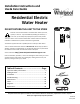
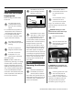
COMPLETED INSTALLATION TYPICAL Water shut off Cold water line Hot water line Expansion tank Energy Smart Module, Electronic Thermostat and Upper Element Electrical junc on box T&P relief valve T&P discharge pipe Lower Element and Thermostat access Drain pan discharge pipe Drain valve Drain pan Drain
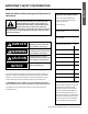
Read and follow all safety messages and instruc ons in this manual. This is the safety alert symbol. It is used to alert you to poten al physical injury hazards. Obey all safety messages that follow this symbol to avoid possible property damage, serious injury or death. Do not remove any permanent instruc ons, labels, or the data plate from either the outside of the water heater or on the inside of the access panels. Keep this manual near the water heater.
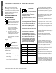
SAFETY IMPORTANT SAFETY INFORMATION T o reduce the risk of property damage, serious injury or death, read and follow the precau ons below, all labels on the water heater, and the safety messages and instruc ons throughout this manual.
According to a na onal standard American Society of San ary Engineering (ASSE 1070) and most local plumbing codes, the water heater’s thermostat should not be used as the sole means to regulate water temperature and avoid scalds. Properly adjusted Thermosta c Mixing Valves installed at each point-of-use allow you to set the tank temperature to a higher se ng without increasing risk of scalds.
GETTING STARTED Review all of the instruc ons before you begin work. If you aren’t sure that you can safely and properly do this work yourself, call your Lowe’s® store to arrange for Professional Installa on (you may also call a qualified person of your choice, such as a licensed plumber or electrician, to have the work done). Improper installa on can damage the water heater, your home and other property, and can present risks of serious injury or death.
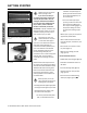
INSTALLATION ✓ Water pressure increase caused by thermal expansion Step 1: ✓ Verify that your home is equipped and up-to-date for proper opera on Installing a new water heater is the perfect me to examine your home’s plumbing system and make sure the system is up to current code standards. There have likely been plumbing code changes since the old water heater was installed.
INSTALLATION INSTALLATION BACKGROUND: Water expands when heated, and the increased volume of water must have a place to go, or thermal expansion will cause large increases in water pressure (despite the use of a Pressure Reducing Valve on the home’s main water supply line). The Safe Drinking Water Act of 1974 requires the use of backflow preventers and check valves to restrict water from your home reentering the public water system.
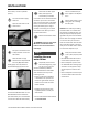
5 The loca on is not prone to physical damage by vehicles, flooding, or other risks. Before installing your water heater, ensure that: 1 2 The loca on has adequate space (clearances) for periodic servicing. 3 The floor can support the weight of a full water heater. Your area is not prone to earthquakes. If it is, use special straps as required by local building codes.
INSTALLATION tank to drain, contact a qualified person.) 7 Turn the cold water supply valve OFF. 8 Open the drain valve on the water heater. Disconnect the water pipes. Many water pipes are connected by a threaded union which can be disconnected with wrenches. If you must cut the water pipes, cut the pipes close to the water heater’s inlet and outlet connec ons, leaving the water pipes as long as possible. If necessary, you can make them shorter later when you install the new water heater.
DO NOT CONNECT ELECTRICAL WIRING UNTIL YOU ARE INSTRUCTED TO DO SO. NOTICE: Connec ng electrical power to the tank before it is completely full of water (water must run FULL STREAM from a hot water tap for a full three minutes) will cause the upper hea ng element to burn out. • The discharge pipe must withstand 250°F (121°C) without distor on. Use only copper or CPVC pipe. Do not use any other type of pipe, such as PVC, iron, flexible plas c pipe, or any type of hose.
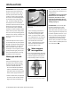
INSTALLATION Step 6: Install shutoff and tempering valves If one is not already installed, install a manual shutoff valve in the cold water line that supplies the water heater. Install the shutoff valve near the water heater so that it is readily accessible. Only use valves that are compa ble with potable water. Use only full-flow ball or gate valves. Other types of valves may cause excessive restric on to the water flow.
2 Full-flow ball valve A Pressure Reducing Valve is required if your home’s water pressure is above 80 psi. NOTICE: Most water heater models contain energy saving heat traps in the inlet and outlet connec ons to avoid the circula on of hot water within the pipes. Do not remove the heat traps. Connect the hot water supply using 3/4 inch NPT to the fi ng marked “H” (HOT). Follow the same connec on guidelines as for the cold water supply.
INSTALLATION Step 9: Make electrical connec ons INSTALLATION WARNING! Working on an energized circuit can result in severe injury or death from electrical shock. NOTICE: The tank must be completely empty of air and full of water before connec ng electrical power to avoid “Dry Firing.” Dry Firing may result in the upper element burning out. This is a common installa on mistake.
Replace the junc on box cover and secure with the screws provided. thermostat, it is located behind the lower access panel. • Fold the insula on back in place and replace the access panels. WARNING! Be sure cover is secured to reduce the risk of fire and electric shock. WARNING! Be sure panels are secured to reduce the risk of fire and electric shock. Step 10: Adjus ng the Temperature Adjust Thermosta c Mixing Valves at each pointof-use to 120°F or lower.
INSTALLATION Step 11: Opera on INSTALLATION The water heater is now ready for normal opera on. To keep your water heater working safely and efficiently and extend its life, perform maintenance according to the schedule on page 29. Vaca on To save energy, lower the temperature se ng on the thermostat(s) if you plan to be gone for an extended me.
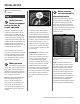
Adjusting the Energy Smart® Module/Operational Modes Water Temperature Adjustment IMPORTANT: Before attempting to adjust the thermostat, read the “Important Safety Information” section on page 4. If the instructions are not clear, contact a qualified service technician. The water temperature can be adjusted from 80° F to 150° F. Use the Up and Down Buttons desired temperature.
INSTALLATION The Electronic Thermostat INSTALLATION IMPORTANT: The Energy Smart® Module (ESM) must be removed before a empting to access the thermostat. NOTE: for the Electronic Thermostat (ET) changes to remain in effect the Energy Smart® Module (ESM) must not be reconnected, also read the “Water Temperature Regula on” under the “Opera ng Your Water Heater” sec on. If the instruc ons are not clear, contact a qualified service technician.
The electric Smart Grid will enable significant improvements in electric power reliability and quality through reduc on of peak power demand, while providing consumers the knowledge and ability to manage their energy consump on and u lity costs. According to the Department of Energy (DOE), since 1982 the growth in peak electricity demand has exceeded power transmission growth.
DIAGNOSTIC CODE CHART Energy Smart® Module (ESM) IMPORTANT: Before attempting to adjust the thermostat, read the “Important Safety Information” section page 4. ENERGY SMART The Electronic Thermostat (ET) is designed so that it may control the water heater without the Energy Smart® Module (ESM) being operated, see page 18. STANDARD VACATION GRID ENABLED Error Code Alert Icon ALERT If the instructions are not clear, contact a qualified person.
(ESM) ERROR CODE INDICATES CORRECTIVE ACTION* E51 with an alert Icon flashing. A failure to communicate with the Electronic Thermostat (ET). E52 with an alert Icon flashing. Energy Smart ® Module (ESM) is receiving the wrong data from the Electronic Thermostat (ET). 1. Turn off electrical power at the breaker, check all electrical connections, and wiring for damage. Energy Smart ® Module (ESM) thermistor failure. 1.
DIAGNOSTIC CODE CHART Electronic Thermostat (ET) Setpoint Knob IMPORTANT: Before attempting to adjust the thermostat, read the “Important Safety Information” Diagnostic section page 4. LED Light The Electronic Thermostat (ET) is designed so that it may control the water heater without the Energy Smart® Module (ESM) being operated, see page 18. If the instructions are not clear, contact a qualified person.
E9 E10 E11 E12 (ET) DIAGNOSTIC LED 9, 10, 11 or 12 FLASHES (Red) INDICATES Electronic Thermostat (ET) error CORRECTIVE ACTION* 1. 2. 3. 4. Turn off electrical power. Check wiring at Electronic Thermostat (ET) for damage. Turn on electrical power at breaker. If this code flashes condition continues, replace the Electronic Thermostat (ET). *These instructions are brief and intended as guidance for a qualified person.
TROUBLESHOOTING PROBLEM POSSIBLE CAUSE(S) See explana ons on the following pages. CORRECTIVE ACTION NO HOT WATER (page 26) • No power to water heater Check for blown fuses or tripped circuit breaker. Check for power. • Burned out upper hea ng element (Dry Fired) Replace upper hea ng element. • Energy Cut Off Switch tripped See page 27, step 5. • Faulty Thermosta c Mixing Valve Check hot water at other faucets. • Non-Func oning upper thermostat Check/replace upper thermostat.
Need Assistance? Call our Technical Assistance Hotline at 1-877-817-6750 . We can help you with installa on, opera on, troubleshoo ng, or maintenance. Before you call, write down the model and serial number from the water heater’s data plate.
TROUBLESHOOTING WARNING! Working near an energized circuit can result in severe injury or death from electrical shock. • Locate the electrical junc on box on top of the water heater and remove the cover. WARNING! When you are finished, be sure all covers are secured to reduce the risk of fire and electric shock. • Iden fy the two power wires. The power wires are usually black/black or black/red—the green or copper wire is the ground wire.
Check/Reset Energy Cut Off (ECO) Bu on. hear a click. In that case, the upper thermostat should be checked by a qualified person. check the water temperature at several faucets to make sure the problem is not in a faucet or shower control. • Replace the insula on and the upper access panel. Thermostats set too low. If the water temperature at several faucets is too cool, adjust the thermostat(s) according to the instruc ons in Step 10 of the Installa on sec on of this manual.
TROUBLESHOOTING rarely, the lower thermostat) is not working, you will have some hot water but not as much as before. Because the lower element does most of the work, the lower element usually wears out before the upper element. Replace the lower element and/or thermostat if necessary (see page 30-31).
MAINTENANCE Rou ne maintenance will help your water heater last longer and work better. If you can’t perform these rou ne maintenance tasks yourself, contact a qualified person. Water Heater Maintenance A er the first six months, drain and flush the water heater and inspect the anode rod. Depending on the hardness of your water, repeat this process at least annually, or more frequently if needed. From me to me you may need to replace a hea ng element or a thermostat.
MAINTENANCE flush the tank. Replace the anode rod if it is substan ally worn out or depleted. Therea er, inspect the anode rod annually or more frequently if needed. If you use a water so ener, your anode rod will deplete faster than normal. Inspect the anode rod more frequently, replacing the anode rod as needed. Obtain new anode rods from Lowe’s® or have a qualified person replace it. (Anode rods are a consumable item and are not covered under warranty).
Remove the upper or lower access panel on the water heater, and then fold back the insula on and remove the plas c element/thermostat cover. 5 complete instruc ons on filling the tank, follow Step 8 in the Installa on sec on. Refill the tank by opening the cold water supply valve. Make sure a hot water faucet is open and the drain valve is closed. Allow the hot water to run full for at least three minutes to make sure the tank has all the air removed and is completely full of water.
MAINTENANCE 11 Replace the cover on the electrical junc on box. 12 Restore power to the water heater. It may take two hours for the tank to heat up. T&P Relief Valve Maintenance Remove the upper or lower access panel on the water heater and carefully fold back the insula on and plas c element/ thermostat cover. 3 4 Make sure the replacement thermostat matches the original thermostat. 5 Mark the wires with tape so you’ll know how to put them back on.
Notes: Call our Technical Assistance Hotline at 1-877-817-6750 . We can help you with installa on, opera on, troubleshoo ng, or maintenance. Before you call, write down the model and serial number from the water heater’s data plate.
DIAGRAMS Thermostat Wiring Diagram FUSED DISCONNECT OR CIRCUIT BREAKER ON JUNCTION BOX COVER RED BLACK BLACK GREEN RED SMART GRID WIRE HARNESS L1 L3 ELECTRONIC THERMOSTAT (ET) L4 T2 T4 UPPER ELEMENT TEMPERATURE SENSOR BLUE BLACK BLACK - 5 WIRES YELLOW BLACK - 2 WIRES BLUE BRANCH CIRCUIT SIZING GUIDE Based on N.E.C. NFPA NO. 70 - 1999 Copper Wire Size Recommend AWG Based on Over Current WATT N.E.C.
This page left blank intentionally.
REPAIR PARTS Repair Part Illustra on 10 9 11 13 4 3 2 8 1 3 12 6 7 5 Repair Parts Repair parts may be ordered through your plumber, local distributor, home improvement center, or by calling 1-877-817-6750. When ordering repair parts, always give the following information: 1. Model, serial and product number 2. Item number 3. Parts description Repair Parts List REPAIR PARTS Legend PARTS DESCRIPTION ITEM No.