
Installation guide


I Put on safety glasses and gloves.
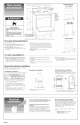
Install exhaust hood.
Use caulking compound to seal --
exterior wall opening around
exhaust hood.
Connect vent to exhaust hood with 4"
clamp. (Exhaust vent MUST fit inside hoodO
Run exhaust vent to dryer location.
Use the straightest path possible. (See Panel B.)
Use clamps to secure vent pieces, Tin snips may be
needed to cut vent to required length,
SLIDE DRYER ONTO
HARDBOARD BEFORE
MOVING ACROSS
FLOOR TO PREVENT
FLOOR DAMAGE,
Excessive Weight Hazard
Use two or more people to move and install dryer.
Faimure to do so can resumt in back or other injury.
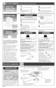
Open dryer door and drying rack, if included.
Wipe drum with damp cloth to remove any dust.
Take two cardboard
corners from dryer carton and _-_
place them on floor in back of
dryer. Firmly grasp body of dryer
and gently lay it on its back on the
cardboard corners,
1 Start to screw legs into holes by hand. Use
an adiustabie wrench or 1" hex-head socket wrench
to finish turning Iegs until you reach the ridge with
the diamond marking.
Stand dryer up on cardboard or hardboard.
This dwer is manufactured with the cabinet-
ground conductor connected to the NEUTRAL
(center) of the wiring harness at the terminal
block. If local codes do NOT permit this type of
connection, use "Four-wire connection"
instructions.
GROUNDING INSTRUCTIONS: This appliance must
be grounded. In the event of malfunction or
breakdown, grounding will reduce the risk of
electric shock by providing a path of least
resistance for electric current.
If using a power supply cord, the plug must be
plugged into an appropriate outlet that is properly
installed and grounded in accordance with all local
codes and ordinances.
If using a direct wire connection, this appliance
must be connected to a grounded metal,
permanent wiring system; or an equipment°
ground conductor must be run with the circuit
conductors and connected to the equipment°
ground terminal or lead on the appliance.
WARNING - Improper connection of the
equipment-grounding conductor can result in a
risk of electric shock. Check with a qualified
electrician or serviceman if you are in doubt as to
whether the appliance is properly grounded. Do
not modify the power supply cord plug. If it will
not fit the outlet, have a proper outlet installed by
a qualified electrician.
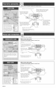
Pewer supply cerd
Fire Hazard
Use a new UL approved 30 ampere power
supply cord.
Use a UL approved strain relief.
Disconnect power before making electrical
connections.
Connect neutral wire (white or center wire}
to center terminal (silver).
Ground wire (green or bare wire} must be
connected to green ground connector.
Connect remaining 2 supply wires to
remaining 2 terminals (gold).
Securely tighten all electrical connections.
Failure to do so can result in death, fire, or
electrical shock.
]. Disconnect the power supply,
hold-down screw
2, Remove holddown
screw and terminal
terminal
block cover, block
cover
extemal ground
conductor screw
Direct wire
Fire Hazard
Use 10 gauge solid copper wire.
Use a UL approved strain relief.
Disconnect power before making electrical
connections.
Connect neutral wire (white or center wire)
to center terminam (sHyer).
Ground wire (green or bare wire} must be
connected to green ground connector.
Connect remaining 2 supply wires to
remaining 2 terminals (gold}.
Securely tighten all electrical connections.
Failure to do so can result in death, fire, or
electrical shock.
strain
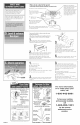
3, Assemble 3/4"
relief
screws just enough to hold screws
the two clamp sections together. Install power
supply cord/cable through the strain relief.
Complete installation following instructions for
your type of connection:
• Fourowire (recommended method)
Three-wire (if four-wire is not available)
Four-wire power supply cord at least four feet
long must have four, NoA 0 copper wires and
match a four-wire receptacle of NEMA Type
14o30R. The fourth wire (ground conductor)
must be identified with a green cover and the
neutral conductor by a white cover.
14-30R Four-wire receptacme (required for mobime homes)
4, Remove center terminal block screw. 5, Remove appliance ground wire (green
_ with yellow stripes) from external ground
z . X connector screw. Fasten under center,
O Connect ground w_re
" _ silver-colored terminal block screw.
(green) of power supply cord to _ /
external ground conductor f- .... "
screw. Tighten screw.
external 9roun
8, Connect the other _Mres to- ; ;
outer terminal block screws.
Tighten screws. _ 7, Connect neutral
9. Tighten strain
relief screws.
1
I U. insert tab of terminal block cover
into slot of the dryer rear panel Secure
cover with hold-down screw.
wire (white or center)
of power supply cord
under center screw of
the terminal block.
Tighten screw.
Panel C