
Installation guide


requirements
Electrical Shock Hazard
Electrical ground is required for
microwave oven hood.
Do Not ground to a gas pipe.
Do Not change the power supply cord
plug. If it does not fit the outlet, have a
proper outlet installed by a qualified
electrician.
Do Not have a fuse in the neutral or
grounding circuit.
Do Not use an extension cord.
Check with a qualified electrician if you
are not sure microwave oven hood is
properly grounded.
Failure to follow these instructions could
result in death or serious injury.
If codes permit and a separate grounding
wire isused, it isrecommended that a
qualified electrician determine that the
grounding path isadequate.
A 120-volt, 60-Hz, AC-only, 15- or 20-ampere,
fused electrical supply (located in the upper
cabinet as close as possible to the microwave
oven hood) is required. A time-delay fuse or
circuit breaker is recommended, tt is
recommended thai" a separate circuit
serving only this appliance be provided.
, Ir
I ,i
I(_l I
I II
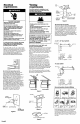
Recommended grounding melhod
For your personal safety, this microwave
oven hood must be grounded. ThiS
microwave oven hood is equipped with a
power supply cord having a 3-prong
grounding plug. To minimize possible shock
hazard, the cord must be plugged into a
mating 3-prong grounding-type wall
receptacle, grounded in accordance with
the National Electrical Code, ANSI/NFPA
70 -- latest edition (*, see Panel A), and all
local codes and ordinances. (See Figure 1.)
If a mating wall receptacle is not available,
it is the personal responsibility and obligation
of the customer to have a properly
grounded, 3-prong wall receptacle
installed by a qualified electrician.
3-pron_l
grounalng plug
/
power
supply cord
grounding prong
Figure I
\
3-prong
groundlng-type
wall receptacle
Panel B
Venting
requirements
Ductwork needed for Installation is not
included. Wall and roof caps used must
have back-draft damper.
Fire Hazard
Venting system must terminate to the
outside.
Do Not terminate the ductwork in an attic
or other enclosed space.
Do Not use 4" laundry-type wall caps.
Do Not use plastic ductwork.
Failure to follow recommended venting
procedures may result in a fire.
r
CAUTION: To reduce risk of fire and
to properly exhaust air, be sure to
duct air outside. Do Not vent
exhaust air into spaces within walls
or ceilings or into attics, crawl
spaces or garages.
Use metal ductwork only. Rigid metal
ductwork isrecommended.
Flexible metal ductwork is Not recommended.
If flexible metal ductwork is used, calculate
each foot of flexible metal ductwork as two
feet of straight metal ductwork. Flexible metal
elbows count twice as much as standard
elbows.
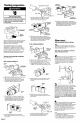
Determine which venting method (roof-
venting or wall-venting) you need to use.
This microwave oven hood is equipped for
ventless (recircuiating) installation.
The length of the ductwork and number
of elbows should be kept to a minimum to
provide efficient performance. The size of
ductwork should be uniform. Do Not install
two elbows together, Use duct tape to seal
all joints in the duct system. Use caulking to
seat exterior wall or roof opening around cap.
Figures 2-5 show common venting methods
and types of materials needed.
Note: If the rear exhaust method is chosen,
be sure that there is proper clearance within
the watl for the exhaust duct.
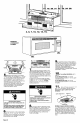
Roof venting
Wall venting
Figure 2
roof caph
3-I/4" x 10"
duct
j,=
through-the-roof
Figure 3
[___ wall cap
3-1/4" X 10" through-the-wall
Figure 4
roof
diameter _ I o°""""[-........
.un00u I
, ' " "_ wall
elbow "** =.o,: cap
3-I/4" to 3-I/4" x I0" to round
round duct ductwork transition
transition
Figure 5
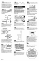
Recommended duct length
Use 3-I/4"x I0"or6"duct.The totallength
of the duct system including straight duct,
elbow, transitions, wall or roof caps must not
exceed the equivalent of 140 feet of 3-1/4"
x 10" rectangular or 6""diameter round duct.
For best performance, use no more than
three 90° elbows, To calculate the length of
system you need, add the equivalent feet
for each duct piece used in the system. See
the following examples:
3- I/4" x I 0" duct system
1 - 3-1/4" x 10"
90° elbow = 25 ft.
1 - wall cap = 40 ft.
8 feet straight = 8 ft.
Length of
3-1/4"x 10" system = 73 ft.
6" duct system
transition
6ft. --
1 - transition = 5 ft,
2 - 90° elbows : 20 ft.
1 - wall cap = 40 ft.
8 feet straight : 8 ft.
Length of 6'"system = 73 ft.
Recommended standard firings
_i_:-,.._i_
: _:..::_:::::_::::::._
-..,.,J.,._!_i.:-:.:-,"
'_:..:i:_
3-1/4" x 1O"
to 6" = 5 ft.
90 ° elbow
= 10 ft.
3-1/4" x 10"
roof cap = 24 ft.
3-1/4" x 1O"
wall cap =
40ft.
.÷:.:.:<*x<_..
_ "_.
3-1/4" x 10"
90 ° elbow = 25 ft
45 ° elbow
=Sft,
3-1/4" x 10"
flat elbow =
10 ft.
If the existing duct is round, a rectangular-
to-round adapter must be used and a
rectangular 3" extension duct between the
damper assembly and the adapter must be
installed to prevent sticking of the exhaust
damper.