
Specifications
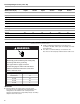

10
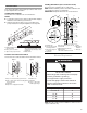
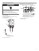
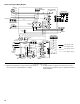
Outdoor Unit Typical Wiring Diagram
Complete Installation
1. Operate the heat pump for a period of at least 15 minutes to
allow for pressures and temperatures to stabilize.
2. If heat pump does not appear to be functioning correctly,
have heat pump checked by a person certified by the EPA to
handle refrigerant.
BK
BK
R
Dual
Capacitor
Defrost Control
Thermostat
Line voltage - Field
Low voltage - Field
Line voltage - Factory
Low voltage - Factory
Ground
Thermostat
S87
Low
Pressure Switch
(if used)
BK
BK
BK
BK
PR
R
Y
Fan
OR
R
Reversing
Valve
Defrost
Thermostat
Ground
Lug
Equipment
Ground
PR
BK
BK
OR
R
Y
Compressor
Crankcase Heater
(if used)
Compressor
Contactor
Outdoor
Fan
BK
Low
Pressure Switch
(if used)
FAN
Fan
High
Pressure Switch
(if used)
High
Pressure
Switch
(if used)
Defrost Control
Reversing
Valve
Defrost
Thermostat
Compressor
Contactor
Coil
Compressor
Crankcase
Thermostat
(if used)
Crankcase
Heater
(if used)
Compressor
Contactor
Defrost
Control
Dual
Capacitor
Outdoor
Fan
COMMON