
Specifications


13
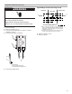
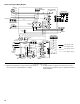
Troubleshoot the Defrost System
Diagnostic LEDs
The defrost board uses 2 LEDs for diagnostics. The LEDs flash a
specific sequence according to the condition.
1. Disconnect power.
2. Remove control box cover.
3. Reconnect power and set thermostat for heating operation.
4. Observe LEDs and compare to Defrost Control Board
Diagnostic LEDs chart.
5. If a system failure is indicated, take appropriate action to
correct.
6. Turn off thermostat and disconnect power.
7. Replace control box cover.
8. Reconnect power.
SYSTEM MAINTENANCE
■ Leaves and other large obstructions should be removed from
the heat pump surfaces without damaging the fin surface of
the coil.
■ Routinely clean or change the indoor air filter. Should the
indoor coil become dirty, thus restricting airflow, call a
qualified service person to clean the coil surface.
■ An annual inspection by a qualified person should be
performed to ensure continued high-quality performance.
ASSISTANCE OR SERVICE
If you need further assistance, you can write to the below
address with any questions or concerns:
Whirlpool
®
Home Cooling and Heating
14610 Breakers Drive
Jacksonville, FL 32258
Please include a daytime phone number in your correspondence.
Accessories
To order accessories contact your Whirlpool
®
Home Cooling and
Heating dealer.
WARNING
Electrical Shock Hazard
Disconnect power before servicing.
Replace all parts and panels before operating.
Failure to do so can result in death or electrical shock.
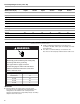
Defrost Control Board Diagnostic LEDs
Mode
Green LED
(DS2)
Red LED
(DS1)
No power to board Off Off
Normal operation/power to board Simultaneous slow flash
Anti-short cycle lockout Alternating slow flash
Low pressure switch fault Off Slow flash
Low pressure switch lockout Off On
High pressure switch fault Slow flash Off
High pressure switch lockout On Off