
Specifications

2
Tools and Parts
Gather the required tools and parts before starting installation.
Read and follow the instructions provided with any tools listed
here.
Tools Needed
Parts Needed
Check local codes and HVAC supplier. Check existing electrical
supply, and read “Electrical Requirements,” “Location
Requirements,” “System Requirements” and “Connect
Refrigerant Lines.”
System Requirements
Heat pump system matches are derived from actual laboratory
testing of matched systems. It is recommended that only
matching equipment be used to ensure proper operation and
efficient performance.
■ The designed system matches are listed in the heat pump
specification sheets and on the heat pump refrigerant
charging instructions located on the back of the service
access panel.
■ Refrigerant charging instructions include a list of matching
indoor equipment with the proper thermal expansion valve
size and amount of refrigerant charge required.
■ This heat pump has been factory charged with a quantity of
refrigerant (R-22) sufficient for a matched indoor coil and a
maximum 15 ft (4.6 m) of refrigerant line.
Indoor System Thermal Expansion Valve
■ Check the indoor coil thermal expansion valve to see whether
it matches the required thermal expansion valve for the
indoor coil and heat pump combination being installed.
■ Refer to the refrigerant charge label located on the inside of
the heat pump access panel for the correct thermal
expansion valve size required.
■ Replace the thermal expansion valve with the correct size if
this size is not already installed in the indoor coil. Instructions
for replacing the thermal expansion valve are provided with
the indoor coil.
Location Requirements
■ This heat pump is designed to be located outdoors with
sufficient clearance for free entrance to the inlet and
discharge air openings. The location must also allow for
adequate service access. See “Minimum Clearances.”
■ Where possible, select a location for the heat pump which is
shaded from the direct rays of the sun most of the time. North
or east locations are usually most desirable. Position the heat
pump to avoid direct contact with water, snow or ice from a
roofline overhead.
■ The heat pump must be installed on a solid, level mounting
pad that will not settle or shift. Isolate the pad from the
building structure to avoid possible transmission of sound or
vibration from the heat pump into the conditioned space.
■ The heat pump foundation should be raised to a minimum of
3" (7.6 cm) above finish grade. In areas which have prolonged
periods of temperatures below freezing, and/or snowfall, the
heat pump should be elevated above the average snow line.
If heat pump is to be installed on a flat roof, it should be on a
platform or other support which will raise the inlet air opening
12" (30.5 cm) minimum above the surface of the flat roof.
■ Avoid ice accumulation by ensuring free drainage of
condensate from defrost cycles. The heat pump should be
located away from walkways to avoid possible icing from
defrost condensate.
■ Avoid placing the heat pump near areas such as sleeping
quarters or study rooms. Normal operating sound levels may
be objectionable if the heat pump is placed near certain
rooms. A shift in sound type does occur during the defrost
mode. The defrost mode generally lasts no longer than
10 minutes.
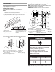
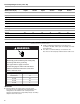
Minimum Clearances
■ Torch
■ ¹⁄₄" (6.4 mm) nut driver
■ ⁵⁄₁₆" (7.6 mm) nut driver
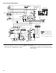
A. Weatherproof disconnect switch
B. NEC class 1 wiring
C. NEC class 2 wiring
D. To power supply
E. House thermostat
F. To indoor unit
G. To indoor coil
H. Seal openings
48" (121.9 cm)
Overhead Clearance
(Discharge Air)
D
F
G
30" (76.2 cm) Service
Access Clearance
36" (91.4 cm)
Clearance (Inlet Air)
12" (30.5 cm) Clearance
Between Unit and Building
12" (30.5 cm)
Clearance (Inlet Air)
AB C E
H