
Specifications

7
Charge Using Approach Method (Thermal Expansion Valve Systems)—Outdoor Temperatures 65°F (18ºC) or Above
Use this method if charging a Thermal Expansion Valve system
when the outdoor ambient temperature is 65ºF (18ºC) or above.
NOTES:
■ The following procedure is intended as a general guide.
■ Use on Thermal Expansion Valve systems only.
■ For best results, indoor temperature should 70°F (21ºC) to
80°F (27ºC).
■ Monitor system pressures while charging.
1. Record outdoor ambient temperature using a digital
thermometer.
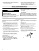
2. Attach high pressure gauge set.
3. Operate condensing unit for several minutes to allow system
pressures to stabilize.
4. Compare stabilized pressures with those provided in the
Normal Operating Pressures chart.
NOTES:
■ Minor variations in these pressures may be expected due
to differences in installations.
■ Significant differences could mean that the system is not
properly charged or that a problem exists with some
component in the system.
■ Pressures higher than those listed indicate that the
system is overcharged.
■ Pressures lower than those listed indicate that the system
is undercharged.
■ Verify adjusted charge using the approach method.
5. Use the same digital thermometer to check liquid line
temperature.
6. Subtract the outdoor ambient temperature from the liquid line
temperature to determine the approach temperature.
_____ ° (Liquid Line Temperature °F) - _____ ° (Outdoor
Ambient Temperature °F) = _____ ° (Approach
Temperature °F)
7. Compare the approach value with those shown in the
Approach Values for Thermal Expansion Valve Systems chart.
■ If the approach values are too high, add refrigerant to
lower the approach temperature
■ If the approach values are too low, recover refrigerant
from the system to increase the approach temperature.
■ Approach value is the liquid line temperature minus the
outdoor ambient temperature (∆°F).
NOTE: For best results, use the same digital thermometer to
check both outdoor ambient and liquid temperatures.
Check Charge Using Normal Operating Pressures
Use the Normal Operating Pressures chart to perform
maintenance checks.
NOTES:
■ This chart is not a procedure for charging the system.
■ Minor variations in these pressures may be due to differences
in installations.
■ Significant deviations could mean that the system is not
properly charged or that a problem exists with some
component in the system.
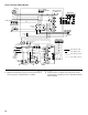
Normal Operating Pressures (-18 to -36)
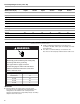
Approach Values for Thermal Expansion Valve Systems
Model W2GH318A W2GH324A W2GH330A W2GH336A W2GH342A W2GH348A W2GH360A
Temperature ºF 7 8911787
W2GH318A W2GH324A W2GH330A W2GH336A
Air Temperature Entering
Outdoor Coil ºF (ºC) Liquid Suction Liquid Suction Liquid Suction Liquid Suction
Cooling
65 (18) 141 81 148 80 146 78 154 78
75 (23.9) 163 82 176 82 171 79 180 88
85 (29.4) 191 84 206 83 201 80 210 99
95 (35) 222 85 240 84 233 81 246 109
105 (40.6) 256 87 277 86 271 81 277 119
115 (46.1) 296 89 322 87 313 83 318 130
Heating
50 (10) 192 64 185 60 198 58 196 58
40 (4.4) 180 53 176 50 188 47 185 47
30 (1.1) 172 43 165 49 175 35 176 37
20 (-6.7) 164 34 162 31 163 26 170 30
NOTE: Values provided are typical pressures. Indoor unit match-up, indoor air quality and indoor load will cause pressures to vary.