
Specifications

9
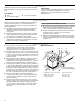
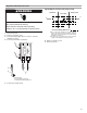
Single Phase Electrical Connections
1. Disconnect power.
2. Remove control box cover.
3. Connect the field supply wires L1 and L2 to contactor
terminals L1 and L2.
4. Connect ground wire to ground lug.
5. Connect low voltage circuit.
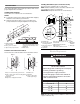
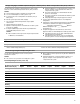
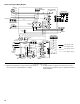
Typical Wiring Connection (low voltage circuit)
6. Replace control box cover.
7. Reconnect power.
A. Ground lug
B. Field supply ground wire
C. 208/230 volt field supply wires
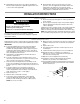
WARNING
Electrical Shock Hazard
Disconnect power before servicing.
Replace all parts and panels before operating.
Failure to do so can result in death or electrical shock.
T1T2
L1L2
L1L2
C
A
B
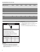
A. Do not connect C (common) connection between
indoor unit and thermostat except when required
by the indoor thermostat. Refer to the thermostat
installation instructions.
B. C (common) connection between indoor unit and
outdoor unit required for proper operation.
R
C
Y
O
W
Thermostat
Indoor Unit
Outdoor Unit
24V Control Wiring (NEC Class 2)
R
C
Y
O
G
R
C
W
G
W
A
B