
Unit installation


13
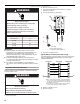
24 VAC Power Wiring
The diagnostic module requires a constant nominal 24 VAC
power supply. The wiring to the module’s R and C terminals must
be directly from the indoor unit or thermostat.
Thermostat Demand Wiring
The diagnostic module requires a thermostat demand signal to
operate properly. The thermostat demand signal input, labeled Y
on the module, should always be connected to the compressor
contactor coil so that when the coil is energized, the demand
signal input is 24 VAC. When the coil is not energized, the
demand signal input should be less than 0.5 VAC.
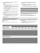
Alert (Yellow) Flash Code 1 Long Run Time: Compressor is
running extremely long run
cycles.
■ Low refrigerant charge.
■ Evaporator blower is not running.
■ Evaporator coil is frozen.
■ Faulty expansion valve.
■ Condenser coil is dirty.
■ Liquid line restriction (filter dryer blocked, if present in the system)
■ Thermostat is malfunctioning.
Alert (Yellow) Flash Code 2 System Pressure Trip: Discharge
or suction pressure out of limits
or compressor is overloaded.
■ High head pressure.
■ Condenser coil has poor air circulation (dirty, blocked, damaged).
■ Condenser fan is not running.
■ Return air duct has substantial leakage.
■ If low pressure switch is present in the system, go to Flash Code 1
information.
Alert (Yellow) Flash Code 3 Short Cycling: Compressor is
running only briefly.
■ Thermostat demand signal is intermittent.
■ Time delay relay or control board is defective.
■ If high pressure switch is present, go to Flash Code 2 information.
■ If low pressure switch is present, go to Flash Code 1 information.
Alert (Yellow) Flash Code 4 Locked Rotor
■ Run capacitor has failed.
■ Low line voltage (contact utility if voltage at disconnect is low).
■ Excessive liquid refrigerant in the compressor.
■ Compressor bearings are seized.
Alert (Yellow) Flash Code 5 Open circuit
■ Outdoor unit power disconnect is open.
■ Compressor circuit breaker or fuse(s) is open.
■ Compressor contactor has failed to open.
■ High pressure switch is open and requires manual reset.
■ Open circuit in the compressor supply wiring or connections.
■ Unusually long compressor protector reset time due to the
extreme ambient temperature.
■ Compressor windings are damaged.
Alert (Yellow) Flash Code 6 Open Start Circuit: Current only
in run circuit.
■ Run capacitor has failed.
■ Open circuit in the compressor start wiring or connections.
■ Compressor start winding is damaged.
Alert (Yellow) Flash Code 7 Open Run Circuit: Current only
in start circuit
■ Open circuit in the compressor run wiring or connections.
■ Compressor run winding is damaged.
Alert (Yellow) Flash Code 8 Welded Contactor: Compressor
always runs.
■ Compressor contactor has failed to close.
■ Thermostat demand signal not connected to the module.
Alert (Yellow) Flash Code 9 Low Voltage: Control circuit less
than 17 VAC
■ Control circuit transformer is overloaded.
■ Low line voltage (contact utility if voltage at disconnect is low).
Flash Codes
LED Status Fault Description Troubleshooting Information