R-110 TECHNICAL EDUCATION 2010 Whirlpool 26’ SXS Refrigerators GSF26C5EXW GSF26C5EXY GSS26C5XXA GSS26C5XXB GSS26C5XXW GSS26C5XXY GSF26C5EXS GSF26C5EXT JOB AID W10338921
FORWARD This Job Aid, Whirlpool Gold 26’ SXS 2010 Part Number W10330404 has been compiled to provide the recent information on design, features, operation, troubleshooting and repair procedures for 26’ SXS for 2010. This Job Aid is not intended to replace or substitute for the Use and Care Guides or Tech Sheets associated with any of the models covered. Refer to the Technical Service sheet shipped with the refrigerator for detailed information for the unit you are servicing.
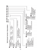
TABLE OF CONTENTS Page GENERAL . . . . . . . . . . . . . . . . . . . . . . . . . . . . . . . . . . . . . . . . . . . . . . . . . . . . . . . . . . . . . . . Safety. . . . . . . . . . . . . . . . . . . . . . . . . . . . . . . . . . . . . . . . . . . . . . . . . . . . . . . . . . . . . . . . . Introduction Specifications and Overview. . . . . . . . . . . . . . . . . . . . . . . . . . . . . . . . . . . . . SxS Model Number Interpretation. . . . . . . . . . . . . . . . . . . . . . . . . . . . . . . . . . . .
TABLE OF CONTENTS (continued) Door Open Alarm . . . . . . . . . . . . . . . . . . . . . . . . . . . . . . . . . . . . . . . . . . . . . . . . . . . . . . . 5-9 Dispenser Lock . . . . . . . . . . . . . . . . . . . . . . . . . . . . . . . . . . . . . . . . . . . . . . . . . . . . . . . . 5-10 Cooling Off Mode. . . . . . . . . . . . . . . . . . . . . . . . . . . . . . . . . . . . . . . . . . . . . . . . . . . . . . . 5-11 Cooling On Mode. . . . . . . . . . . . . . . . . . . . . . . . . . . . . . . . . . . . .
GENERAL Safety Observe all safety warnings and messages. The Use and Care manual and Installation instructions that come with the product as well as stickers and literature attached to the refrigerator contain safety symbols. These symbols contain messages telling you of potential hazards and explain how to reduce your chance of injury. The message will also tell you what can happen if the instructions are not followed. Your safety and the safety of others are very important.
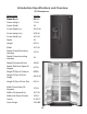
Dimensions Inches.
1-3
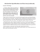
Introduction Specifications and Overview (continued) 6th Sense Technology 6th Sense software makes an estimation of the actual food temperature inside the refrigerator and freezer compartment and adjusts cooling to allow the food packages to return their initial temperature faster during pull down, door openings, or heavy food load. 6th Sense algorithm runs in both freezer compartment and refrigerator compartment and each contains 3 routines: Trigger, Package Estimator, and Defrost Manager.
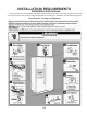
INSTALLATION REQUIREMENTS Installation Instructions This new SXS platform requires different installation steps and adjustments than current SXS refrigerators. Review the Use and Care manual and instruction sheets shipped with the product prior to installation.
Installation Instructions (continued) Installation - Example hex 2-2
Installation Instructions (continued) Installation - Example (continued) 2-3
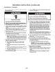
Installation Refrigerators are shipped with the handles packed in the refrigerator door. 1. Remove the handles from the door and unwrap. 1 2. The instruction sheet and a Hex key tool are attached to the handle. Review the instruction sheet. 2 3. Install the handle on the mounting studs with the hex screws facing to the center. 3 4. Hold the handle tight against the door as you tighten the screws. The handle will pull in tight against the door as the screw is tightened.
Installation Instructions (continued) Installation (continued) Removing Grille WARNING Electrical Shock Hazard Disconnect power before servicing. Replace all parts and panels before operating. Failure to do so can result in death or electrical shock. 1. Disconnect power to the refrigerator. Remove 2 ¼” screws The grille is held in place with 2 ¼” screws. 2. Remove screws 2 Remove grille 3. Open the doors 90 degrees perpendicular to the cabinet to remove the grille.
Installation Instructions (continued) Removing Freezer Door WARNING Electrical Shock Hazard Disconnect power before servicing. Replace all parts and panels before operating. Failure to do so can result in death or electrical shock. 2 1. Unplug or disconnect the refrigerator from the power supply. onnect water tubes form the de of the connector 2. Remove the screws securing the wire harnesses to the cabinet. 32 3. Disconnect water tubes form the door side of the connector. 4.
Installation Instructions (continued) Removing Freezer Door Upper Hinge 6. Remove Two 3/16” hex key screws (A). Do not remove or loosen the other two screws (B). 7. Keep the door closed and lift off the hinge. B A A B 65 WARNING Excessive Weight Hazard Use two or more people to lift the freezer door. Failure to do so can result in back or other injury. Lift off the hinge 76 8. Have another person open the freezer door and lift up slowly. 87 9.
—NOTES— 2-8
REFRIGERATOR COMPONENTS Refrigerator Compartment Light Bulbs Air Damper Air Filter Water Filter Disassembling Refrigerator Compartment Components WARNING 2 1 Electrical Shock Hazard Disconnect power before servicing. Replace all parts and panels before operating. Failure to do so can result in death or electrical shock. 1. Disconnect power to the refrigerator. 32 2. Open the water filter door and remove the filter. 3. Open the air filter door and remove the filter. 4.
Refrigerator Compartment (continued) 3 5. Remove the air damper cover. 54 6. Remove the ¼” screw securing the air filter housing to the cabinet and remove. 65 7. Disconnect the wiring harness and remove the air damper assembly. 76 8. Check the seal around the damper housing for any damage or misplace ment. Replace or reposition seal as needed.
Refrigerator Compartment (continued) Disassembling Refrigerator Compartment Components – Water Filter Housing Remove the water filter as explained earlier. 1. Remove the ¼” screw securing the filter cover to the filter body. 1 2. Remove the cover. 2 3. Remove the ¼” screw securing the filter body to the cabinet wall. 3 4. To replace the filter housing, disconnect the water tubes in the back of the refrigerator and remove Permagum seal.
Refrigerator Compartment (continued) Refrigerator Thermistor The refrigerator Thermistor is a variable resistance device connected to the control board. The temperature of the refrigerator compartment causes the resistance of the Thermistor to change. The resistance is monitored by a circuit on the control board which controls the operation of the cooling system. The Thermistor is located on the right side of the refrigerator cabinet attached to the back of the cover labeled 6th sense.
Refrigerator Compartment (continued) Replacing Refrigerator Thermistor 1. Depress the tabs on either end of the Thermistor cover and remove. 2. To replace the Thermistor order replace ment Thermistor kit through the normal part ordering system by model number. Follow the instructions supplied with the kit.
Refrigerator Compartment (continued) Disassembling Refrigerator Compartment Components – Accessing Water Reservoir Disassembling Refrigerator Compartment Components – Accessing Water Reservoir 1. The light bulb cover is very flexible and can be bent to release the 4 tabs that extend into the cabinet wall and remove. 1 2. To replace the water reservoir, Shut off water supply. 3. Remove the ¼” hex head screw and the wire ties securing the reservoir to the cabinet. 3 2 4.
Freezer Compartment and Ice Maker Freezer Components Freezer Thermistor The freezer Thermistor is a variable resistance device connected to the control board. The temperature of the freezer compartment causes the resistance of the Thermistor to change. The resistance is monitored by a circuit on the control board which controls the operation of the cooling system. The Thermistor is located on the left side of the freezer cabinet attached to the back of the cover labeled 6th sense.
Freezer Components (continued) Replacing Freezer Thermistor 1. Depress the tabs on either end of the Thermistor cover and remove. 2. To replace the Thermistor order replacement Thermistor kit through the normal part ordering system by model number. Follow the instructions supplied with the kit.
Freezer Components (continued) Accessing Freezer Components WARNING Electrical Shock Hazard Disconnect power before servicing. Replace all parts and panels before operating. Failure to do so can result in death or electrical shock. 1. Unplug refrigerator or disconnect power. Remove food and shelving. 2. Pull off the light cover located in the top left hand corner of the freezer compartment. 3. Remove the ¼” hex head screw below the light bulb. 4.
Freezer Components (continued) Accessing Freezer Components (continued) 5. Remove the 4 - 1/4” hex head screws securing the evaporator to the cabinet. 5 6. Pull out the evaporator cover.
Freezer Components (continued) Removing Evaporator Fan Motor 1. Slide out the evaporator fan motor assembly from the built in cabinet rails and disconnect the wiring harness. 1 2. To change the fan blade, pull the blade off the shaft and replace. When installing the blade, push the blade down on the shaft until it bottoms out. 2 3. Unclip the mounting bracket from the fan shroud to remove the motor. 3 4-5 Continued next page.
Freezer Components (continued) Checking evaporator fan motor WARNING Electrical Shock Hazard Disconnect power before servicing. Replace all parts and panels before operating. Failure to do so can result in death or electrical shock. Unplug refrigerator or disconnect power. The evaporator fan motor is a 120 VAC shaded pole motor. To check, remove the 2 wires from the motor. Connect an Ohmmeter across the motor leads. The resistance measured should be approximately 135 Ohms plus or minus 10%.
Freezer Components (continued) Checking Defrost Bimetal WARNING 2 Electrical Shock Hazard Disconnect power before servicing. Replace all parts and panels before operating. Failure to do so can result in death or electrical shock. 1 Disconnect power to the refrigerator. 1. Slide the defrost bimetal off the coil. 2. Disconnect the wiring harness. 3. Disconnect the green chassis ground wire attached to the evaporator heat shield. 4.
Freezer Components (continued) Replacing the defrost heater Disconnect power to the refrigerator. 1. Remove evaporator cover as explained earlier. 2. Disconnect the two black wires connected to the defrost heater. 3. Disconnect the green chassis ground wire attached to the evaporator heat shield. 4. Grasp the bottom of the heat shield all pull out. The heat shield is fastened to the cabinet with clips and will pull out easily. 5.
Freezer Components (continued) Freezer Door Component Location A label on the freezer instructs the customer the ice maker ON/OFF switch is located behind the ice storage bin. Ice maker Ice maker Specifications • IDI XXL design uses W10122576 120VAC ice maker • 6 cavity small cube ice maker (similar to Tempest ice maker, but mounts in freezer door and has splash provisions) • Fill volume: 49cc • Harvest frequency: 42 minutes normally, 35 minutes Accelerice • Ice bin capacity 4.0 lbs.
Freezer Components (continued) Ice maker – Emitter /Receiver Boards The emitter board emits an infrared beam. When the eye on the receiver board sees the beam a circuit is completed indicating the ice bin is in place and not full. This signal is sent to the control board and the ice maker is energized. If the beam is not seen by the receiver board, the control board shuts off the ice maker. 1.
Freezer Components (continued) WARNING Electrical Shock Hazard Disconnect power before servicing. Replace all parts and panels before operating. Failure to do so can result in death or electrical shock. 1. Disconnect power to the refrigerator. 2. Depress the ice bin latch and remove the ice bin.
Freezer Components (continued) 3. Remove 2 - 1/4” screws securing the housing to the inner door panel. Lift the housing up and out to remove. 3 4. When assembling insert the tabs located on the top of the housing into the slots on the inner door panel.
Freezer Components (continued) Accessing New In Door Ice Maker 5. Remove the ice maker wire harness cover and disconnect the harness. 5 6. Disconnect the wire harness to the emitter and receiver boards. 6 7. Remove 2 - 1/4” screws under the ice maker. 7 8. Slide out the ice maker to remove. 8 9. Remove 3 - ¼” screws to remove housing from the ice maker mold.
Freezer Components (continued) Accessing New In Door Ice Maker 10. Unplug the wire harness from the ice maker head. 10 11. Slide off the Hi Limit control from the mold.
Freezer Components (continued) Ice maker New Six Cavity Ice Maker Component Identification Bracket Head Ice Stripper Ejector Blade Module Mold Components Disassembling the ice maker. 1. Remove the ice maker cover. A module similar to the existing product is used. The module is checked exactly as the cur rent module. Refer to ice maker tech sheet shipped with the product” See next page. n 2. Remove three screws that secure the module to the head.
h Sheet Do not DANGER Freezer Components (continued) WARNING DANGER WARNING Electrical Shock Hazard Electrical Shock Hazard nly authorized technicians should perform diagnostic oltage measurements. Electrical Shock Hazard Only authorized technicians should fter performing voltage measurements, perform diagnostic voltagedisconnect measurements. ower before servicing. After performing voltage measurements, ailure to follow these instructions can result in death or disconnect power before servicing.
Freezer Components (continued) 4-17
Freezer Components (continued) Disassembling the ice maker (continued) 2 3. Separate the module from the head. 3 4. Remove two screws on the bottom of the ice maker head and separate the head from the mold. The thermostat can be removed at this point. 4 5. When replacing the thermostat apply a coating of Alumilastic to the mold. This will provide a thermal bond between the mold and thermostat.
Freezer Components (continued) Replacing Auger Motor and Related Components 1. Remove 2 screws and lift off cover. 1 2. Remove the coupling by lifting straight up. A spring is captured under the coupling. Coupling Spring 2 3. To access the motor remove the 4 - 1/4” screws securing the chute to the housing. 3 4. Lift out the chute. The chute may require some effort to remove because of the foam seal around the chute tube. 4 5. Inspect seal and repair or replace if necessary before reassembly.
Freezer Components (continued) Removing Auger Motor 6. Remove 4 - 1/4” screws securing the motor to the housing . 6 7. Lift up the auger motor and disconnect the wire harness. 7 Condensate Drain Under normal operating conditions, moisture may accumulate in the bottom of the auger motor housing. A drain hole is provided to allow water to pass through the inner door panel and drop onto the lower shelf, see figure 2.
Freezer Components (continued) Checking the Auger Motor WARNING Electrical Shock Hazard Disconnect power before servicing. Replace all parts and panels before operating. Failure to do so can result in death or electrical shock. Unplug refrigerator or disconnect power. Connect an Ohmmeter across the 2 motor terminals and measure the resistance. The resistance should be approximately 210 Ohms plus or minus 10%.
Freezer Components (continued) Water Tube Routing Water Routing: the home water supply is connected to the isolation valve. The outlet of the isolation valve connects to the water filter located in the refrigeration compartment. The outlet of the filter connects to the inlet of the water reservoir. The water reservoir outlet connects to the inlet of the dual valve. Freezer Door The ice maker fill tube and the water dispenser tube are routed through the hole in the lower freezer door hinge.
DISPENSER AND USER INTERFACE Stealth Control Figure 1 – Whirlpool Stealth User Interf ace/Blue LED’s except as noted. The Icons used on this Whirlpool user interface display are similar to those used on other SXS models but not identical. The basic operation and programming is the same.
Programming (continued) Figure 3 – KitchenAid Interface Icon Identification Figure 3 depicts all the ICONS and Text located on the Display. Specific Icons will be displayed at different steps during programming as explained in this manual. Sleep Mode The display screen on the dispenser control panel will turn off automatically and enter “sleep” mode when the control buttons and dispenser levers have not been used for 2 minutes or more. See figure 4.
Programming (continued) Figure 5 Pressing any control button will activate the “Normal/Home ” display screen, without changing any settings. See figure 5. After activation, changes to any settings can then be made. If no changes are made within 2 minutes, the display will re-enter “sleep” mode. Factory Preset Temperatures The refrigerator and freezer controls are preset at the factory. The factory recommended set points are 37°F (3°C) for the refrigerator and 0°F (-18°C) for the freezer.
Programming (continued) Adjusting Temperature Set Points: Figure 7 Pressing and holding TEMPERATURE starts a 3 second countdown. During the countdown using the dispenser cancels the countdown and no dispensing is permitted. The number 3 blinks 3 times and an invalid tone sounds 3 times,. The user has to release both the pad and the button and press the button again to start the countdown over. During the countdown, pressing any other button or releasing the pad cancels the countdown.
Programming (continued) Figure 8 Adjusting Temperature Settings Press the LOCK pad to raise the temperature set point or press the MAX ICE pad to lower the temperature set point. See figure 8. IMPORTANT: When the temperature is changed, the word “CONFIRM” above the filter reset pad illuminates and will flash without an audible tone constantly until user presses RESET FILTER, ICE MODE or after 60 seconds of inactivity.
Programming (continued) Figure 10 Ice Dispenser: Ice dispenses from the ice maker storage bin in the freezer when the dispenser lever is pressed. The ice maker can produce both crushed and cubed ice. Before dispensing ice, select which type of ice you prefer by pressing the ICE MODE button. The display screen indicates which type of ice is selected. See figure 10. For crushed ice, cubes are crushed before being dispensed. This may cause a slight delay when dispensing crushed ice.
Programming (continued) Figure 11 Max Ice: The Max Ice feature assists with temporary periods of heavy ice use by increasing ice production over a 24-hour period. IMPORTANT: This feature only works if the ice maker is turned on. Press MAX ICE to turn on this feature. When the feature is on, the Max Ice icon will appear on the dispenser display screen. See figure 11. The Max Ice setting will remain on for 24hours unless manually turned off.
Programming (continued) Figure 12 Dispenser Light: When you use the dispenser, the light will automatically turn on. If you want the light to be on continuously, you may choose either ON or DIM. The display screen indicates which mode is selected. See figure 12. ON: Press LIGHT to turn the dispenser light on at 100% DIM: Press LIGHT a second time to select DIM mode. The dispenser light will remain on, but at a lower 50% intensity.
Programming (continued) Figure 13 Door Open Alarm The Door Open Alarm feature sounds an alarm when the refrigerator or freezer door is open for 5 minutes and the product cooling is turned on. The alarm will repeat every 2 minutes. Close both doors to turn it off. The feature then resets and will reactivate when either door is left open again for 5 minutes. Details: When a door is open for 5 minutes and the cooling function is on: The Door Open Icon and the normal screen is displayed.
Programming (continued) Figure 14 Dispenser Lock: The dispenser can be turned off for easy cleaning or to avoid unintentional dispensing by small children and pets. NOTE: The lock feature does not shut off power to the refrigerator, to the ice maker, or to the dispenser light. It simply deactivates the controls and dispenser levers. Details: Pressing and holding LOCK starts a 3 second countdown. During the countdown, using the dispenser cancels the countdown and no dispensing is permitted.
Programming (continued) Figure 15 Cooling Off Mode Pressing and holding both LOCK and RESET FILTER simultaneously, see figure 15, starts a 3, 2, 1 second countdown. During the countdown, using the dispenser cancels the countdown AND no dispensing is permitted. After 3 seconds, the ‘cooling off’ icon appears and flashes 7 times then remains on. All the rest of the icons including door open turn off. Exception: if the UI is locked the user can still turn cooling off.
Programming (continued) Figure 16 Water Filter Status Light: The water filter status light will help you know when to change your water filter. When the dispenser control panel’s water filter status display changes to “ORDER,” this tells you that it is almost time to change the water filter cartridge. Replace the water filter cartridge when the water filter status display changes to “REPLACE.” The filter should be replaced at least every 6 months depending on your water quality and usage.
Programming (continued) Figure 17 Showroom Mode: Pressing and holding LIGHT and MAX ICE starts a 3 second countdown. During the countdown, pressing any other button or releasing a pad cancels the countdown. Details: After 3 seconds, the control enters the showroom mode and the cooling system turns off. When in the showroom mode, cooling off and WFI icons stay off all the time, while the Door Open icon appears whenever door is open, however there is no door open audible alert.
Dispenser Components Accessing User Interface and Dispenser Components WARNING Electrical Shock Hazard Disconnect power before servicing. Replace all parts and panels before operating. Failure to do so can result in death or electrical shock. 1. Disconnect power to the refrigerator. 2. Remove the drip tray and the grille. 2 Location of tabs 3 3. Release 3 locking tabs securing the user interface to the dispenser housing.
Dispenser Components (continued) 4. Drop down the User Interface board. 4 5. Remove the wire harnesses. 5 6. Remove the 4 screws securing the dispenser housing to the door panel. 6 7. Disconnect the water tube from the dispenser assembly.
Dispenser Components (continued) 8. Remove 2 - 1/4" hex head screws securing the dispenser assembly to the door panel. 8 9. Remove the wiring harnesses from the dispenser bracket. Remove the wire harnesses. 9 Lef t Clip 10. Release the retaining clips on the left and right side of the dispenser assembly. Right Clip 10 2" 11. Pull the top of the dispenser housing out about 2” to allow removal of the dispenser assembly. 11 12. Remove two screws to replace the dispenser motor.
Dispenser Components (continued) 13. The dispenser door can be snapped out to replace. 13 NOTE: The door can be replaced without removing the assembly. Depress Here 14. To replace a switch, depress the release in the center slot and slide off the switch.
—NOTES— 5-18
MACHINE COMPARTMENT WARNING Electrical Shock Hazard Disconnect power before servicing. Replace all parts and panels before operating. Failure to do so can result in death or electrical shock. Unplug refrigerator or disconnect power." Gum Seal Wrapped Around Water Tubes Water Tubes to Water Filter.
Machine Compartment Components WARNING Electrical Shock Hazard Disconnect power before servicing. Replace all parts and panels before operating. Failure to do so can result in death or electrical shock. 1. 2. Disconnect power to the refrigerator. Remove the ¼” screws securing the fiber cover to the cabinet. 3. To remove the start module remove the bail and unplug the module. 2 2 3 3 4. Unplug the wire harness. 4 4 5. The run capacitor unplugs from the module.
Machine Compartment Components (continued) Starting Device Operation The starting device is an assembly consisting of an overload (1) and a PTC relay (2). The PTC relay is composed of a semi conductive substance formed in the shape of a disk (2). The disk is connected in series with the run and start terminals which in turn connect to the run and start windings. The resistance of the disk material is relatively low at room temperature.
Machine Compartment Components (continued) Accessing Dual Water Valve: The valve is located in the machine compartment attached to the compartment wall. To Remove: WARNING Electrical Shock Hazard Disconnect power before servicing. Replace all parts and panels before operating. Failure to do so can result in death or electrical shock. 1. Unplug the refrigerator or disconnect power. 2. Unsnap the water valve assembly out of the bracket. 2 3.
Machine Compartment Components (continued) Condenser Fan: The condenser fan motor is a step motor and cannot be checked with an Ohmmeter. The condenser fan blade can be pulled off to replace without removing the assembly. Wire Harness To remove the condenser fan motor: WARNING Electrical Shock Hazard Disconnect power before servicing. Replace all parts and panels before operating. Failure to do so can result in death or electrical shock. Screws 1. Unplug the refrigerator or disconnect power. 2.
Machine Compartment Components (continued) Drain Pan The drain pan is much larger than anything that has been used recently. It’s secured to the bottom of the cabinet with 5 1/4" screws.
Machine Compartment Components (continued) Front Wheel A center wheel assembly replaces the tradition corner wheel design used on other models. WARNING Excessive Weight Hazard Use two or more people to move and install refrigerator. Failure to do so can result in back or other injury. Axle The axle is held in place by a locking clip. The refrigerator must be tilted back to remove. Locking clip Clip To remove the wheel: 1.
Machine Compartment Components (continued) Control and Power Supply Boards Similar to existing refrigerators, the control and power supply boards are located behind a cover on the back of the refrigerator. To access the boards: WARNING Electrical Shock Hazard Disconnect power before servicing. Replace all parts and panels before operating. Failure to do so can result in death or electrical shock. 2 1. Disconnect the refrigerator from the power supply. 3 2.
DIAGNOSTICS, WIRING DIAGRAMS AND TROUBLESHOOTING 7-1
Diagnostics, Wiring Diagrams And Troubleshooting (continued) 7-2
FOR SERVICE USE ONLY Diagnostics, Wiring TECHNICIAN’S Diagrams And Troubleshooting h Sheet (continued) Do no For Service Technician's Use Only Voltage Test Points DANGER DANGER WARNING WARNING Electrical Shock Hazard Electrical Shock Hazard Only authorized technicians perform diagnostic Only authorizedshould technicians should oltage measurements. perform diagnostic voltage measurements.
Diagnostics, Wiring Diagrams And Troubleshooting (continued) Voltage Test Points (continued) GEMINI FLASH 7-4
Diagnostics, Wiring Diagrams And Troubleshooting (continued) 7-5
Diagnostics, Wiring Diagrams And Troubleshooting (continued) For Service Technician's Use Only WARNING Electrical Shock Hazard Disconnect power before servicing. Replace all parts and panels before operating. Failure to do so can result in death or electrical shock. Unplug refrigerator or disconnect power.
Diagnostics, Wiring Diagrams And Troubleshooting (continued) 7-7
Diagnostics, Wiring Diagrams And Troubleshooting (continued) 7-8
PRODUCT SPECIFICATIONS AND WARRANTY INFORMATION SOURCES IN THE UNITED STATES: FOR PRODUCT SPECIFICATIONS AND WARANTY INFORMATION CALL: FOR WHIRLPOOL PRODUCTS: 1-800-253-1301 FOR KITCHENAID PRODUCTS: 1-800-422-1230 FOR ROPER PRODUCTS: 1-800-447-6737 FOR TECHNICAL ASSISTANCE WHILE AT THE CUSTOMER’S HOME CALL: THE TECHNICAL ASSISTANCE LINE: 1-800-253-2870 HAVE YOUR STORE NUMBER READY TO IDENTIFY YOU AS AN AUTHORIZED SERVICER FOR LITERATURE ORDERS: PHONE: 1-800-851-4605 FOR TECHNICAL INFORMATION AND SERVICE POI