SuperStor Ultra Indirect Fired Water Heaters INSTALLATION START-UP MAINTENANCE PARTS For Residential and Commercial Use This manual must only be used by a qualified installer/service technician. Read all instructions in this manual before installing. Perform steps in the given order. Failure to comply could result in substantial property damage, severe personal injury, or death.
The following defined terms are used throughout this manual to bring attention to the presence of hazards of various risk levels, or to important product information. DANGER indicates an imminently hazardous situation which, if not avoided, will result in death or serious injury. WARNING indicates a potentially hazardous situation which, if not avoided, could result in death or serious injury.
PART 3 – PIPING ...................................................................................................................................................................... 11 A. PLUMBING ............................................................................................................................................................................... 11 B. BOILER CONNECTIONS ...............................................................................................................
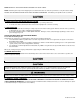
NOTE: OBTAIN ALL APPLICABLE PERMITS AND OBEY ALL LOCAL CODES. NOTE: Install all system components and piping in such a manner that does not reduce the performance of any fire rated assembly. DO NOT USE THIS WATER HEATER IF ANY PART HAS BEEN UNDERWATER. Immediately call a qualified service technician. Any claims for damage or shortage in shipment must be filed immediately against the transportation company by the consignee. B.
PRODUCTS TO AVOID Spray cans containing fluorocarbons Permanent wave solutions Chlorinated waxes/cleaners Chlorine-based swimming pool chemicals Calcium chloride used for thawing Sodium chloride used for water softening Refrigerant leaks Paint or varnish removers Hydrochloric or Muriatic acid Cements and glues Antistatic fabric softeners used in clothes dryers Chlorine-type bleaches, laundry detergents, and cleaning solvents Adhesives used to fasten building products Table 1 – Chemical Contaminants AREAS
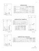
Figure 1 – Dimensions LP-83 Rev. 8.14.
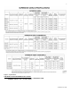
Figure 2 - Specifications CONTINUOUS FLOW PERFORMANCE CALCULATION FIRST HOUR RATING – (.75 X TANK CAPACITY) = CONTINUOUS FLOW EXAMPLE: SSU-45C = 314 – (.75 X 45) = 280.25 LP-83 Rev. 8.14.
A. REDUCED BOILER INPUT SIZING GUIDE NOTE: IT IS NOT RECOMMENDED TO REDUCE BOILER INPUT WHEN USING DOUBLE WALL TANKS.
B. PERFORMANCE AND SIZING GUIDELINES NOTE: TABLE 5 DESCRIBES MINIMUM BTU/H REQUIRED TO ACHIEVE THE LISTED FIRST HOUR RATING.
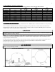
NOTE: If you do not provide the minimum clearances shown in Figure 3, it might not be possible to service the heater without removing it from the space. This water heater must not be located near flammable liquids such as gasoline, butane, liquefied propane, adhesives, solvents, paint thinners, etc., as the controls of this water heater could ignite these vapors and cause an explosion, resulting in property damage, severe personal injury, or death. D.
dissolved solids in excess of 2,000 ppm is a non-warrantable condition. Failure of a water heater due to lime scale build up IS NOT covered by the warranty. Hardness: 7 grains Chloride levels: 100 ppm pH levels: 6-8 TDS: 2000 ppm Sodium: 20 mGL PART 3 – PIPING A. PLUMBING It is mandatory that all plumbing be done in accordance with federal, local, and state plumbing codes and practices. Failure to properly install the water heater WILL VOID the warranty.
6” above the structural floor. The relief line cannot be in contact with any live electrical parts. If the relief valve constantly weeps, install an expansion tank, and see expansion tank manufacturer’s instructions for suggestions. Do not thread a cap or plug into the relief valve under any circumstances! Explosion and property damage, serious injury, or death may result.
discharge temperature by mixing cold and hot water in branch supply lines. Such valves are available from your local plumbing supplier. Table 6 details the relationship of water temperature and time with regard to scald injury and may be used as a guide in determining the safest water temperature for your applications. F. POTABLE EXPANSION TANK A potable hot water expansion tank may be required to offset heated water expansion.
H. PIPING NOTES: 1. Minimum pipe size should match connection size. Upsize pipe accordingly if greater flow is required. 2. A thermal expansion tank suitable for potable water must be sized and installed within this piping system between the backflow preventer and the cold water inlet. 3. All circulators should have an integral flow check. 4. Drains and check valve between unit and storage tank will assist in purging air from system. 5. This drawing is meant to demonstrate system piping only.
NOTES: 1. Minimum pipe size should match connection size. Upsize pipe accordingly if greater flow is required. 2. A thermal expansion tank suitable for potable water must be sized and installed within this piping system between the backflow preventer and the cold water inlet. 3. All circulators should have an integral flow check. 4. Drains and check valve between unit and storage tank will assist in purging air from system. 5. This drawing is meant to demonstrate system piping only.
Figure 6 – Zoning with Zone Valves NOTES: 1. Minimum pipe size should match connection size. Upsize pipe accordingly if greater flow is required. 2. A thermal expansion tank suitable for potable water must be sized and installed within this piping system between the backflow preventer and the cold water inlet. 3. All circulators should have an integral flow check. 4. Drains and check valve between unit and storage tank will assist in purging air from system. 5.
Figure 7 – Zoning with Circulators NOTES: 1. Minimum pipe size should match connection size. Upsize pipe accordingly if greater flow is required. 2. A thermal expansion tank suitable for potable water must be sized and installed within this piping system between the backflow preventer and the cold water inlet. 3. All circulators should have an integral flow check. 4. Drains and check valve between unit and storage tank will assist in purging air from system. 5.
Figure 8 – Typical Installation with Storage Tank NOTES: 1. Minimum pipe size should match connection size. Upsize pipe accordingly if greater flow is required. 2. A thermal expansion tank suitable for potable water must be sized and installed within this piping system between the backflow preventer and the cold water inlet. 3. All circulators should have an integral flow check. 4. Drains and check valve between unit and storage tank will assist in purging air from system. 5.
Figure 9 – Typical Installation with High Efficiency Boiler NOTES: 1. Minimum pipe size should match connection size. Upsize pipe accordingly if greater flow is required. 2. A thermal expansion tank suitable for potable water must be sized and installed within this piping system between the backflow preventer and the cold water inlet. 3. All circulators should have an integral flow check. 4. Drains and check valve between unit and storage tank will assist in purging air from system. 5.
Figure 10 – Typical Dual Purpose Application w/ Wood Boiler Figure 11 – Typical Dual Purpose Application NOTES: 1. Minimum pipe size should match connection size. Upsize pipe accordingly if greater flow is required. 2. A thermal expansion tank suitable for potable water must be sized and installed within this piping system between the backflow preventer and the cold water inlet. 3. All circulators should have an integral flow check. 4.
Figure 12 – Dual Purpose Application with Wood Stove Figure 13 – Dual Purpose Application with Solar Panel NOTES: 1. Minimum pipe size should match connection size. Upsize pipe accordingly if greater flow is required. 2. A thermal expansion tank suitable for potable water must be sized and installed within this piping system between the backflow preventer and the cold water inlet. 3. All circulators should have an integral flow check. 4.
Figure 14 – Typical Steam Boiler - NOTE: On Typical Steam Boiler applications, the SSU indirect heat exchanger supply and return connections must be below the water line from the boiler connection. The internal flow check or spring check must be used to avoid thermal siphoning from the connected boiler. A basket strainer should also be used to avoid sludge and sediment getting into the pump or heat exchanger.
Figure 16 – Typical Multiple Tank Installation NOTES: 1. Minimum pipe size should match connection size. Upsize pipe accordingly if greater flow is required. 2. A thermal expansion tank suitable for potable water must be sized and installed within this piping system between the backflow preventer and the cold water inlet. 3. All circulators should have an integral flow check. 4. Drains and check valve between unit and storage tank will assist in purging air from system. 5.
When wiring the water heater and controls, be sure to label all wires for ease of future maintenance. Wiring errors can cause improper and dangerous operation. C. WIRING DIAGRAMS Figure 17 – Wiring with Circulators Figure 18 – Wiring with Zone Valves LP-83 Rev. 8.14.
ZONING WITH CIRCULATORS – 4845 RELAY Figure 19 – Zoning with Circulators – 4845 Relay ZONING WITH CIRCULATORS USING R8182D AND DPST – NO RELAY REQUIRED Figure 20 – Zoning With Circulators Using R8182D and DPST – No Relay Required LP-83 Rev. 8.14.
ZONING WITH CIRCULATORS USING L8124 A, C, AND R845A RELAY Figure 21 – Zoning with Circulators Using L8124 A, C, and R845A Relay ZONING WITH CIRCULATORS USING L8124 E, F, AND DPST CONTROL – NO RELAY REQUIRED Figure 22 – Zoning with Circulators Using L8124 E, F, and DPST Control – No Relay Required LP-83 Rev. 8.14.
ZONING WITH CIRCULATORS – R182D AND R845A RELAY Figure 23 – Zoning with Circulators – R182D and R845A Relay CONTROL WITH BUILT-IN DPST SWITCH – NO RELAY REQUIRED Figure 24 – Control with Built-In DPST Switch – No Relay Required LP-83 Rev. 8.14.
ZONING WITH CIRCULATORS USING L8124 A, C, AND R845A RELAY Figure 25 – Zoning with Circulators Using L8124 A, C, and R845A Relay ZONING WITH CIRCULATORS USING L8124 A, C, AND DPST – NO RELAY REQUIRED Figure 26 – Zoning with Circulators Using L8124 A, C, and DPST – No Relay Required LP-83 Rev. 8.14.
USING L8148A OR L8152A COLD START BOILER CONTROL WITH CIRCULATORS Figure 27 – Using L8148A or L8152A Cold Start Boiler Control with Circulators PRIORITY ZONE WITH CIRCULATORS Figure 28 – Priority Zone with Circulators LP-83 Rev. 8.14.
USING L8148A OR L8152A COLD START BOILER CONTROL WITH ZONE VALVES Figure 29 – Using L8148A or L8152A Cold Start Boiler Control with Zone Valves PRIORITY ZONE WITH ZONE VALVES Figure 30 – Priority Zone with Zone Valves LP-83 Rev. 8.14.
PART 5 – START-UP AND OPERATION 1. Fill the water heater by opening the cold water shut-off valve. Purge air from the system by opening a hot water outlet at a fixture in a kitchen or bathroom. When water flows freely from the outlet, the system is purged. 2. Check the system for leaks. Fix any leaks before continuing the installation. Any leaks can result in serious property damage and personal injury. 3.
Figure 31 –Parts MODEL SSU-20 SSU-30 SSU-30LB SSU-45 SSU-60 SSU-80 SSU-119 #1 – T&P RELIEF VALVE TP1500 (Not Included) TP1500 (Not Included) TP1500 (Not Included) TP1500 (Not Included) TP1500 (Not Included) TP1400 (Included) TP1400 (Included) #2 – CONTROL WELL PMW-3SENP-1 PMW-3SENP-1 PMW-3SENP-1 PMW-3SENP-1 PMW-3SENP-1 PMW-3SENP-1 PMW-3SENP-1 SSU-45C SSU-60C SSU-80C SSU-119C TP1400 (Included) TP1400 (Included) TP1400 (Included) TP1400 (Included) PMW-3SENP-1 PMW-3SENP-1 PMW-3SENP-1 PMW-3SENP-1 TP15
PART 6 – MAINTENANCE AND TROUBLESHOOTING Periodic maintenance should be performed by a qualified service technician to assure that all the equipment is operating safely and efficiently. The owner should make necessary arrangements with a qualified heating contractor for periodic maintenance of the heater. Installer must also inform the owner that the lack of proper care and maintenance of the heater may result in a hazardous condition.
TROUBLESHOOTING NO HOT WATER PROBLEM Zone valve not opening Circulator not operating Tank control set too low Boiler control set too low Wiring incorrect Tank control failure Zone valve failure Circulator failure Air trap in loop POSSIBLE SOLUTION Open manually to replace.
HTP CUSTOMER INSTALLATION RECORD FORM The following form should be completed by the installer for you to keep as a record of the installation in case of a warranty claim. After reading the important notes at the bottom of the page, please also sign this document.