
Venting Specification


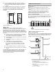

Table Of Contents
- dryer venting specifications
- dryer Safety
- installation requirements
- WARNING: To reduce the risk of fire, this dryer MUST BE EXHAUSTED OUTDOORS.
- NOTE: This guide is intended to aid licensed HVAC or Architectural Engineers who design single and multi-dryer unit venting systems for Whirlpool Corporation dryers sold in the United States. Whirlpool Corporation provides required airflow and back p...
- Outside Exhaust
- The four basic reasons for exhausting a dryer outdoors are detailed in this section:
- The following codes should be reviewed to ensure dryer vent systems are in compliance:
- There are other codes requiring dryers to be exhausted when installed in confined spaces where specified clearances from combustible surfaces cannot be met. See the Installation Instructions for the specific dryer model being used or considered for s...
- Local codes and ordinances that exist must also be met. Consult your local building inspector for more information.
- A normal towel load contains some residual water when it is removed from the washer. The dryer must remove this water and discharge it from the drum. When the dryer is not exhausted outside, this moist air will be recirculated through the dryer, redu...
- Exhausting moisture into the room can also cause damage to walls, floors, picture hangers, and cause condensation on windows and walls in cold weather.
- Even though the dryer is equipped with a lint screen, fine particles of lint will pass through the screen and be exhausted out of the dryer. Proper venting of the dryer will keep lint from accumulating in the laundry area.
- In order to remove moisture from the garments in the dryer, heat is generated to vaporize the water. Exhausting the dryer outdoors removes excess heat from the laundry area of the building.
- Central Exhaust System Requirements
- Exhaust individual dryers to the central exhaust duct system with proper size vents to assure adequate performance of each dryer. The dryer has 4" (102 mm) exhaust duct connections. Connect each dryer to the central vent with a 4" (102 mm) diameter a...
- Install weighted dampers on each individual dryer exhaust duct. These dampers may be used for balancing out the overall duct system.
- Design the central duct system for sufficient capacity to handle the maximum number of dryers operated at one time.
- Consider moisture, lint and air temperature in the design of the central duct system. Maximum exhaust temperature of the dryer will not exceed 200°F (93.3°C) when the dryer is operated according to the instructions provided with the dryer.
- Provide for periodic inspection and clean-out of lint accumulated in the central duct system.
- The capacity to handle up to 230 CFM (cubic feet per minute) of air flow for each dryer in the system.
- A minimum back pressure of -0.1" (-2.5 mm) water column (vacuum) when measured at the connection to the dryer.
- Provide maximum back pressure, based on the maximum rated vent length shown in the Installation Instructions included with dryer. Maximum Allowable Back Pressure chart lists maximum rated vent length and back pressure.
- The minimum duct air velocity during normal operating conditions should be at least 1,200 FPM (feet per minute) to keep lint moving through the vent. (In a 4" (102 mm) diameter pipe, this requires at least 105 CFM of air flow.)
- Measuring and Verifying Actual System Back Pressure
- Back pressure should be measured with an empty dryer, a clean lint screen and with the dryer operating in the Air Only cycle (no heat). Use an inclined manometer, such as Dwyer model 102 (0"-2" [0 mm - 51 mm] range) or Dwyer model 172 (0"-1" [0 mm - ...
- Maximum Allowable Back Pressure for Dryer
- Maximum Rated Vent Length without 90° Elbows (determined from product literature)
- Maximum Allowable Back pressure at connection to dryer (no clothes loaded and clean lint screen)
- 36-37 ft
- 0.40" Water Column
- 64 ft
- 0.60" Water Column
- 100 ft
- 0.80" Water Column
- 120 ft
- 1.00" Water Column
- 130 ft
- 1.10" Water Column
- Back pressure should be measured with an empty dryer, a clean lint screen and with the dryer operating in the Air Only cycle (no heat). Use an inclined manometer, such as Dwyer model 102 (0"-2" [0 mm - 51 mm] range) or Dwyer model 172 (0"-1" [0 mm - ...
- Single Dryer Venting Systems
- Single dryer venting systems are defined as systems that have only one dryer unit attached to a residential-type 4" (102 mm) diameter rigid metal vent system. For single dryer venting systems, see the Installation Instructions for the specific dryer ...
- In cases in which the Installation Instructions do not address the vent length for the specific number of elbows required for a particular application, the following calculations may be used. (The total vent system length includes all straight and cu...
- Measuring and Verifying Actual System Back Pressure
- For 90° elbows, reduce the allowable vent system length by 10 ft (3.05 m).
- For 45° elbows, reduce the allowable vent system length by 6 ft (1.83 m).
- For example, if the Installation Instructions state that a dryer is allowed 40 ft (12.2 m) of total vent length with two 90° bends, and the installation requires three 90° bends, the total allowable vent length would be reduced by 10 ft (3.0 m) (fr...
- The airflow of a dryer depends on the design of the exhaust vent. Each dryer model has a maximum rated vent length, shown in the product literature that is supplied with each model, or on the Whirlpool.com website. The exhaust airflow of any Whirlpoo...
- All Whirlpool electric dryer models, including “long vent dryers,” Turbo Vent™ dryers and combo washer/dryer units that are sold in the United States and Canada are UL listed (reference UL 2158 standard), and all Whirlpool gas dryer models are ...
- Closets used for dryer installation must provide multiple openings to allow air to flow through the dryer and around the dryer to dissipate heat. Any dryer enclosure or room that does not have an inlet and outlet for an operating forced air HVAC syst...
- *Required spacing
- The dimensions shown are for the minimum spacing allowed.
- Additional spacing should be considered for ease of installation and servicing.
- Additional clearances might be required for wall, door, and floor moldings.
- Additional spacing of 1" (25 mm) on all sides of the dryer is recommended to reduce noise transfer.
- For closet installation, with a door, minimum ventilation openings near the top and bottom of the door are required. Louvered doors with equivalent ventilation openings are acceptable.
- Companion appliance spacing should also be considered.
- *Recommended spacing.
- Certain electronic dryer models have airflow detection capabilities. (See specific model product literature for details). If the airflow in the dryer is extremely low, an “AF” code will be displayed on the control panel. For single dryer venting ...
- For multi-dryer venting systems, the “AF” code means that your vent may be blocked or partially blocked or that the venting system is creating back pressure in excess of the maximum allowed. In this case, the engineering firm that designed the sy...
- Multiple Dryer Venting Systems
- Multiple dryer venting systems must be designed specifically for each application.
- NOTE: It is recommended that an architectural or HVAC engineering firm be consulted for designing the dryer venting system.
- Connecting a number of dryers to a single vent system is common in coin-laundry stores and in many apartment buildings. Listed here are some requirements for examples of three different multiple dryer venting systems.
- The most common is the horizontal system, in which banks of dryers are all located in one room and vented through a common duct. See the following illustration for an example of a generic horizontal system.
- The vertical system is used in some apartment buildings that have a washer and dryer on each floor. Each dryer is exhausted into the same central vertical duct. See the following illustration for an example of a generic vertical system.
- The combination system may be used in high-rise apartments, with a bank of dryers installed at several different levels. Each of these banks then exhausts into a central vertical vent. See the following illustration for an example of a combination sy...
- Dryer inspection and cleaning
- Frequency of Exhaust System Cleaning
- Every exhaust system must be inspected periodically and cleaned to ensure that it is intact and free from lint accumulation. The frequency of these inspections will vary, depending on the system and usage of the dryer. For single-family usage, an ann...
- Inspecting the Exhaust System
- 1. Disconnect the exhaust duct from the dryer and from the exhaust hood (at the exhaust outlet) outside of the building.
- 2. Inspect the interior of the duct and remove any lint accumulation.
- 3. Reassemble the exhaust duct and hood, checking that the joints are secure.
- 4. Operate the dryer and verify that the exhaust air is not obstructed in the vent and that there are no leaks in the system.
- ® Registered Trademark/TM Trademark of Whirlpool, U.S.A.
- Inspecting the Exhaust System

5
■ Provide maximum back pressure, based on the maximum
rated vent length shown in the Installation Instructions
included with dryer. Maximum Allowable Back Pressure chart
lists maximum rated vent length and back pressure.
■ The minimum duct air velocity during normal operating
conditions should be at least 1,200 FPM (feet per minute) to
keep lint moving through the vent. (In a 4" (102 mm) diameter
pipe, this requires at least 105 CFM of air flow.)
Measuring and Verifying Actual System Back Pressure
Back pressure should be measured with an empty dryer, a clean
lint screen and with the dryer operating in the Air Only cycle
(no heat). Use an inclined manometer, such as Dwyer model
102 (0"-2" [0 mm - 51 mm] range) or Dwyer model 172
(0"-1" [0 mm - 25 mm] range) to measure the Back Pressure.
See the following illustration.
A. Dryer - empty and running on Air Only cycle
B. 12" (305 mm) min. of straight pipe - measure
bac
k pressure from the center
C. To vent system
D. Location on back pressure measurement
E. Inclined manometer
Maximum Allowable Back Pressure for Dryer
Maximum Rated Vent
Length without 90° Elbows
(determined from product
literature)
Maximum Allowable
Back pr
essure at connection
to dryer (no clothes loaded
and clean lint screen)
36-37 ft 0.40" Water Column
64 ft 0.60" Water Column
100 ft 0.80" Water Column
120 ft 1.00" Water Column
130 ft 1.10" Water Column
Single Dryer Venting Systems
Single dryer venting systems are defined as systems that have
only one dryer unit attached to a residential-type 4" (102 mm)
diameter rigid metal vent sy
stem. For single dryer venting
systems, see the Installation Instructions for the specific dryer
model being used or considered to determine the allowable length
and number of elbows for the venting system.
Additional Elbows
In cases in which the Installation Instructions do no
t address the
vent length for the specific number of elbows required for a
particular application, the following calculations may be used.
(The total vent system length includes all straight and curved
portions of the vent system.):
■ For 90° elbows, reduce the allowable vent system length by
10 ft (3.05 m).
■ For 45° elbows, reduce the allowable vent system length by
6 ft (1.83 m).
For example, if the Insta
llation Instructions state that a dryer is
allowed 40 ft (12.2 m) of total vent length with two 90° bends, and
the
installation requires three 90° bends, the total allowable vent
length would be reduced by 10 ft (3.0 m) (from 40 ft [12.2 m] to
30 ft [9.1 m]).
Dryer Airflow
The airflow of a dryer depends on the design of the exhaust vent.
Each dryer mo
del has a maximum rated vent length, shown in the
product literature that is supplied with each model, or on the
Whirlpool.com website. The exhaust airflow of any Whirlpool
produced dryer at the maximum rated vent length is at least
105 CFM. The maximum airflow is
230 CFM. This includes
standard vent and long vent dryer models.
Codes Agency Approvals
All Whirlpool electric dryer model
s, including “long vent dryers,”
Turbo Vent™ dryers and combo washer/dryer units that are sold
in the United States and Canada are UL listed (reference UL 2158
standard), and all Whirlpool gas dryer models are CSA listed
(reference ANSI Z21.5.1 standard). These standards require
testing at the maximum-rated exhaust vent conditions that are
published in the product literature for each individual model. The
designation for the UL or CSA listing can be found on or adjacent
to the serial label on the product.
Dryer Closet Installations
Closets used for dryer installation must provide multiple openings
to a
llow air to flow through the dryer and around the dryer to
dissipate heat. Any dryer enclosure or room that does not have an
inlet and outlet for an operating forced air HVAC system is
considered a closet, and requires room venting. The room venting
can be installed into the walls of the dryer enclosure, as well as
the door, provided it will not be blocked after the dryer is installed.
Refer to the product literature for minimum clearances between
the product and the enclosure surfaces. Refer to ANSI Z21.5.1
section 2.14.1.
Recommended room venting and spacing
for non-stacked installations
A. Side view - closet or confined area
B. Closet door with vents
*Required spacing
Installation spacing for r
ecessed area or closet
The dimensions shown are for the minimum spacing allowed.
■ Additional spacing should be considered for ease of
installation and servicing.
■ Additional clearances might be required for wall, door, and
floor moldings.
■ Additional spacing of 1" (25 mm) on all sides of the dryer is
recommended to reduce noise transfer.