
Instruction for Use


16
Check the Seal
Once the appliance has been installed, make sure all the
connections are properly sealed, using a soapy water
solution. Never use a flame.
Electrical Connection
The cooktops fitted with a tripolar electrical supply cord are
designed to be be used with alternating current according to
the indications on the rating plate located under the cooktop.
The earthing wire can be identified by its yellow-green colour.
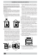
In the case of installation over a built-in electric oven, the
electrical connections for the cooktop and oven should be
independent, not only for safety purposes, but also to
facilitate removal of one or both in the future.
Electrical Connection for Gas Cooktop
Fit the supply cord with a standard plug for the demand rate
indicated on the rating plate or connect it directly to the
electrical mains. In the latter case, a single pole switch must
be placed between the appliance and the mains, with a
minimum opening between the contacts of 3 mm in
compliance with current safety codes (the earthing wire must
not be interrupted by the switch). The power supply cord
must be positioned so that it does not reach a temperature
in excess of 50°C above room temperature at any point.
Before making the actual connection, make sure that:
• The fuse and electrical system can withstand the load
required by the appliance;
• That the electrical supply system is equiped with an
efficient earth hook-up according to the norms and
regulations prescribed by law;
• That the plug or switch is easily accessible.
Important: the wires in the mains lead are coloured in
accordance with the following code:
Green & Yellow - Earth
Blue - Neutral
Brown - Live
As the colours of the wires in the mains lead may not
correspond with the coloured markings identifying the
terminals in your plug, proceed as follows:
Connect the Green & Yellow wire to the terminal marked “E”
or
or coloured Green or Green & Yellow.
Connect the Brown wire to the terminal marked “L” or coloured
Red.
Connect the Blue wire to the terminal marked “N” or coloured
Black.
Adapting the Cooktop for Different Types of Gas
To adapt the cooktop to a different type of gas than that for
which it was designed, (see the sticker under the hob or on
the packaging), the burner nozzles must be changed, as
follows:
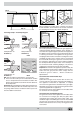
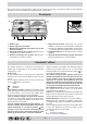
• Remove the pan supports and slide the burners out of
the cooktop.
• Unscrew the nozzles using a 7mm socket wrench and
replace them with those for the new type of gas. (See
table 1, “Burner and Nozzle Specifications”).
• Reassemble the parts following the instructions in reverse
order.
• On completing the operation, replace the old rating label
with the one showing the new type of gas; the sticker is
available from our Service Centres.
If the gas pressure is different than that prescribed, a pressure
regulator must be installed at the source, in compliance with
national standards governing the use of piped gas regulators.
Regulation of Air Supply to the Burner
The burners do not need a primary air regulator.
Minimum Regulation
• Turn the gas valve to minimum.
• Remove the knob and turn the regulator screw (positioned
either on the side of the top or inside the shaft) clockwise
until the flame becomes small but regular.
N.B.: In the case of liquid gas, the regulation screw must be
fully screwed in (clockwise).
• Make sure that, when the knob is turned rapidly high to
low, the flame does not go out.
• In the event of a malfunction on appliances with the
security device (thermocouple) when the gas supply is
set at minimum, increase the minimum supply levels using
the regulator screw.
Once the adjustment has been made, apply sealing wax, or
a suitable substitute, to the old seals on the by-pass.