I AiVhirlDool CONSUMER SERVICES TECHNICAL EDUCATION GROUP PRESENTS ■ Large-Capacity Thin Twin Laundry System Part No. 4314124 Rev. A ikers. Dishwashers, Built-in Ovens and Surface Units.
Whirlpool Regional Headquarters (760) 662-S078 Http://vuww.servicematters.
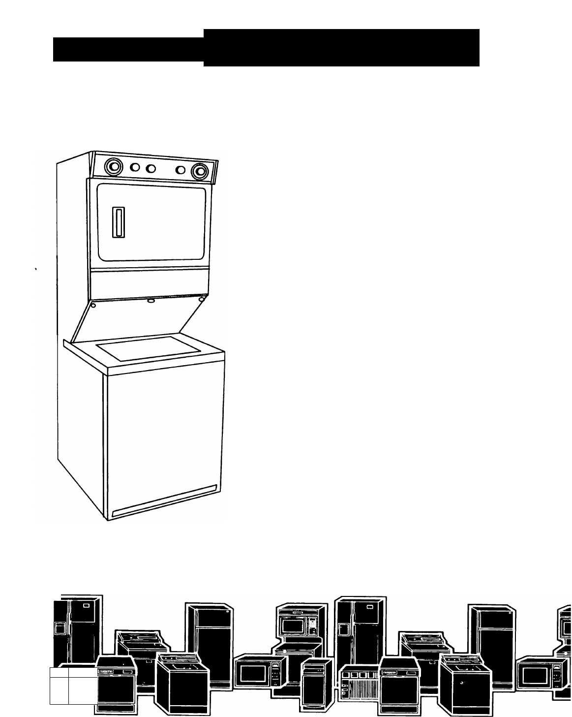
INTRODUCTION This Job Aid, “LARGE-CAPACITY THIN TWIN LAUNDRY SYSTEM,“ (Part No. 4314124 Rev. A) provides specific information for the installation, service and repair of the large-capacity Thin Twin Laun dry system containing both an automatic washer and clothes dryer in one cabinet. ‘‘LARGE-CAPACITY THIN TWIN LAUNDRY SYSTEM” has been compiled to provide the most recent information on design, features, troubleshooting, service and repair procedures.
TABLE OF CONTENTS INTRODUCTION.................................................................................................. TABLE OF CONTENTS ................................................................................... SAFETY............................................................................................................. II Ill IV SECTION ONE INSTALLATION CONSIDERATIONS Removing the Laundry System from the Carton.......................................
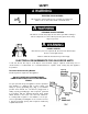
SAFETY A WARNING ELECTRIC SHOCK HAZARD >4V Disconnect the electrical power before servicing any components . Failure to do so can result in death or electrical shock. A WARNING PERSONAL INJURY HAZARD This unit has several sharp edges in areas where you will be working to remove components for service. Wear protective gloves where sharp edges are present.
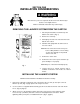
ELECTRICAL REQUIREMENTS FOR ELECTRIC DRYER UNITS A. A three-wire (Fig. 2) or four-wire (Fig. 3), single phase, 120/240 volt, 60 Hz, AC only electrical supply is required on a separate 30-ampere circuit, fused on both sides of the line. A time-delay fuse or circuit breaker is recommended. B. Most local codes permit the use of flex ible, 30-amp rated, power supply cord (pig tail). The power cord must be plugged into a mating 30-amp receptacle (NEMA type 10-30R). A U.
A WARNING Fire Hazard Do Not use nonmetal, flexible duct. Do Not use metal duct smaller that four inches in diameter. Do Not use exhaust hoods with magnetic latches. Improper air supply for exhausting may result in a fire. Check that the exhaust system is not longer than specified. Exhaust systems longer than specified will: • Accumulate lint • Shorten the life of the product • Reduce performance and result in longer drying times and increased energy usage.
SECTION ONE INSTALLATION CONSIDERATIONS A WARNING INJURY HAZARD More than one person is required to lift, tilt or move the washer/dryer because of its weight and size Failure to follow this instruction may result in injury REMOVING THE LAUNDRY SYSTEM FROM THE CARTON 1. Cut along the dotted line around the top and bottom of the carton. (Fig. 1) 2. Remove the carton top. 3. Carefully lay the unit on its side and remove the bottom of the carton. 4.
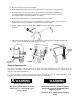
4. Wet the inside of the drain hose with water. DO NOT USE ANY OTHER LUBRICANT. 5. Squeeze the ears of the drain hose clamp with a pair of pliers and place the clamp over the end of the drain hose. (Fig. 2 - Inset A) 6. While holding the clamp open, work the end of the drain hose onto the drain connector. 7. Position the clamp over the drain hose area marked “clamp.” Release the clamp. Clamp should be 14” from the end of the hose. (Fig.
13. Move the washer to its permanent location. 14. Tilt the washer forward off the floor and set back down to adjust the rear self-leveling legs. 15. Check the washer for level, both side-to-side and front-to-back. Adjust the front legs as necessary. Tighten the locking nuts to the base of the washer with a wrench. If the nuts are not tightened, the washer may vibrate excessively. 16. Run water through both faucets to get rid of particles in the water lines. 17. Attach the hoses to the water faucets.
Preparing the Laundry System for Exhausting Left or Right 1. Remove left or right side panel knockout by drilling four (4) holes at the drill locations (dimples) shown and knock out plug. (Fig. 6) Use a file and remove the small burrs in the hole created after the knockout is removed. 2. Remove the two (2) 5/16-inch screws securing the exhaust pipe bracket to the laundry system. Remove the factory installed exhaust pipe from the blower housing collar. Save the exhaust pipe bracket and screws for use later.
4. Preform the flex pipe to the left or right. Pull the flexpipe through the knockout opening until the clip “snaps” into place. (Fig. 9) 5. Maintain the position of the dip with one hand and secure the screw with the other hand. Make sure the screw is snug against the flex pipe, but do not break through. (Fig. 10} NOTE: The flex pipe may also be used to exhaust down or straight out the back. In these cases, the clip is not needed. SCREWDRIVER Fig. 9 6.
-NOTES -
SECTION TWO COMPONENT ACCESS A WARNING Electrical Shock Hazard iIk Disconnect electric power from appliance before servicing. Replace all panels before operating. «¡i w Failure to do so could result in death or electrical shock. Washer Access Front Panel Removal 1. Remove the Transition Panel by removing the three (3) retaining screws. Tip the panel down and lift it out. (Fig. 11) Transition Panei 2. Release the two washer top retaining clips and slide the washer top forward off the unit.
Washer Mechanism Removal 1. Remove the two (2) Vi washer retaining bolts. (Fig. 14) Fig. 14 Retaining Bolts 2. Remove the Motor Wiring and Wiring Harness Clip. (Fig. 15) ^ M. Fig. 15 Motor Wiring Harness 3. Remove the Drain Hose from the retainer (Fig. 16) Drain Hose Retainer 4. Remove the Pressure Hose. (Fig. 17) Fig.
5. Lift and pull the washer assembly forward out of the cabinet. From this position it is possible to service all the washer components, which are similar to those used in other Whirlpool direct drive washers. 6. When reinstalling the washer mechanism, it is important to insure that the base restraints are properly positioned and that the wiring harness, drain hose, vacuum break, and pressure hose are properly installed and positioned. Dryer Access A WARNING ill.
Dryer Toe Panel Access 1. Remove the Transition Panel by removing the three (3) retaining screws. 2. Using a putty knife, release the two (2) retaining clips and remove the toe panel. (Fig. 20) Fig. 20 Door Front Panel Access 1. Remove the transition panel and the Toe Panel. 2. Flip down the Control Panel. (Fig. 22) 3. Disconnect the Door Switch Wires. 4. Remove the Control Panel from the Front Pane! and set it on top of the unit. (Fig. 23) Door Switch Wires Fig.
Screw 5. Remove the top two (2) retaining screws. 6. Remove the bottom two (2) screws. 7. Remove the Lint Screen. 8. Remove the three (3) Dryer Lint Duct assembly retaining screws and remove the assembly. Screw (Fig. 24) 9. Remove the four (4) heater element shield screws. (Fig. 24) 10. The Dryer Front Panel can now be removed. Lint Duct Assembly Heater Element Shield Fig. 24 Retaining Screws Dryer Drive Motor Access 1. Remove the Toe Panel. 2. Remove the Dryer Lint Screen. 3.
Motor Wiring 6* Remove the Blower Housing. 7. Remove the Drive Belt. 8. Remove the Motor Wiring. (Fig. 26) 9. Remove the wiring to the broken belt switch. 10. Remove four (4) motor bracket retaining screws and remove the motor. Dryer Heater Element Access 1. Remove the Dryer Toe Panel. 2. Remove the Lint Screen and the Lint Duct Assem bly and Transition Duct. 3. Remove the Heater Element Shield screws and re move the shield. 4.
Dryer Belt Replacement 1. Remove the Dryer Toe Panel. 2. Remove the Lint Filter and the Lint Duct Assembly. 3. Remove the Blower Assembly. 4. Remove the Dryer Front Panel. Drum Idler Pulley 5. A new Drive Belt can now be looped over the Dryer Drum. (Fig. 27) 6. Loop the Drive Belt over the Drive Motor Pulley. (Fig. 29) 7. Puli the Tension Pulley up and place the belt on it so that the belt is tight when the pulley is released.
-NOTES - 14
SECTION THREE TROUBLESHOOTING and DIAGNOSIS DRYER TROUBLESHOOTING GUIDE CONDITION Dryer will not run. POSSIBLE CAUSE No power to unit. Door switch not making. Thermal fuse open. Broken belt or belt switch. Timer Motor Push-to-start switch No heat in dryer. Improper voltage supply. Heater Element Gas Burner Thermostat Thermal cut-off, Hi-limit Thermostat Motor centrifugal switch Check voltage supply. Check door switch siring and continuity. Check fuse continuity.
TROUBLESHOOTING and DIAGNOSIS WASHER TROUBLESHOOTING GUIDE PROBLEM 1 MOTOR WILL NOT RUN NOTE: in diagnosing this problem, start the washer. If the motor runs in either agi tate or drain, the motor is OK. 2.
POSSIBLE CAUSE PROBLEM 7. KNOCK DURING AGITATE. 8. TRIES TO AGI TATE DURING SPIN. Agitator splines worn Excessive clearance on pinion thrust or main drive gear Shift actuator or cam damaged Replace agitator Replace gearcase Replace gearcase 9. WATER DOES NOT DRAIN FROM MACHINE. Clogged drain Pump Drain hose kinked Remove obstruction Replace pump Relocate hose to prevent kink 10. SLOW OR NO SPIN.
13. CLOTHING DAMAGE Excessive use of bleach Overloading of machine Foreign objects Water level too low Agitates during spin Agitator surface rough Basket surface rough Instruct customer Instruct customer Remove Increase water level See problem 8 Replace agitator Replace basket 14. GEARCASE LEAKS OIL Leak at aaitator shaft Leak at cover seal Too much oil in gearcase Defective cover Replace seal Reseal Use only 13-15 ounces in gearcase Replace cover 15.
CENTRrFUGAL SWITCH To test the centrifugal switch, remove the pump and disconnect the motor harness block from the centrifugal switch. Remove the switch from the motor, and remove the internal motor wires from the centrifugal switch. Set the meter on the R X1 scale and test the switch in the “starf position by pushing up on the switch actuator. Continuity should be present between the red and black terminals and between the orange and blue terminals.
Check the high-speed windings by testing between the blue and white wires. A resistance reading between 3/4 ohm and 2 ohms should be present. Check the low-speed winding by testing between the violet and the white wire. A resistance reading between 1 1/2 and 3 ohms should be present. Check the overload by testing between the white and white-black wires. There should be 0 ohms resistance. START CAPACITOR To test the start capacitor, remove the wires from the capacitor leads.
WATER LEVEL SWITCH To test the water level switch, remove the wires from the water level switch. With the tub empty, there should be continuity from violet to pink and no continuity between violet and tan. With the tub full, there should be continuity from violet to tan and no continuity from violet to pink. WASHER TIMER To test the timer contacts, select the contacts to be tested; in this case, contact 10.
DRYER TIMER To test the timer contacts, select the contacts to be tested; in this case, TM-OR. Using the cycle sequence chart as a reference, turn the timer to the position where the contacts will be closed. (AUTO HI HEAT) E LECTRIC AND GAS DRYER TIMER SCHEDULE CYCLE SWITCH TIMED-HI TIMED-LO CLOSED AUTO-HI HEATAUTO-LO HEAT AIR OFF TM-WB 1 t:' .t BK-BU-V BK-BU BK-R [EITHER NOT BOTH H DOESN’T MATTER ^ CLOSED OPEN There should be continuity between the contacts.
DRYER MOTOR and BROKEN BELT SWITCH To check out the motor, first remove the motor harness from the centrifugal switch. Then, set the meter on the R X 1 scale and check the start winding for continuity. A resistance reading between two (2) and four (4) ohms should be present. The broken belt switch is attached to the dryer drive motor bracket. To check the broken belt switch, set the meter scale to Rx1 and place the probes on the switch terminals. Move the belt pulley up and down to actuate the switch.
HI-LIMIT THERMOSTAT The hi-limit thermostat is located on the side of the heater element (gas burner) housing. To test the hi-limit thermostat at room temperature, set the resistance scale to Rx1 and place the probes on the terminals with the red and red/white wires. The meter should read continuity, (0) ohms resistance. This is because this thermostat is normally closed and will open at temperatures above 250“ F. HEATER 11,2 - THERMAL FUSE The thermal fuse is located on the blower housing.
THERMAL CUT-OFF (Electric Models Only) The thermal cut-off is located on the side of the heater element housing. To test the thermal cut-off, set the resistance scale to Rx1 and place the probes on the terminals with the red wires. The meter should read continuity, (0) ohms resistance. This is because this thermal cut off is normally closed and will open at temperatures above 350“ R If the thermal cut-off is open {infinite resistance) it must be replaced. THERMAL CUT-C MOT MESETTAB 3SO-F heater 11.
GAS BURNER Remove the harness plug from the gas valve terminals and measure the resistance across the termi nals indicated in the following chart.
SECTION FOUR TECHNICAL TIPS WASHER CAM i8 sw. 10 13 12 T 8 o: § TIMER SCHEDULES 10 TBTBTs 5Hl 5 2 i 14 7 7 14 ~ £fc fc; a. Q- s o -J 0 R_ > K W U, 11 12 108 X LU i :=> 120 SECONDS PER STEP §i$w BK-W lU ~2 7 7 A 7 7 6 6 7 7.5 !£ Of MACHINE FUNCTION FiLL-AGtTATE HI FILL 4 WASH fill-agitate hi FILL 4 WASH J 1: 1 6 ±=i SPIN HI 12 fillzgitate hi DRAIN Hf SPRAY 0FF If} -fi. Z -Zj -fiZi Zi 4 22 coaDowi FÌLLZGFTATE LO r ?R g DRAIN HI 2£ Jl to CO LU OCQ.
Wiring Diagram - Eiectric Dryer Modeis 28
Wiring Diagram - Gas Dryer Models 29
MODEL/SERIAL NUMBER PLATE LOCATION The model/serial number plate for the Whirlpool Thin Twin Laundry System is located in the dryer door opening.
“ NOTES - 31
-- NOTES - 32
Whifl CORPORATION Making your world a little easier.