30" (76.2 CM) AND 36" (91.4 CM) RETRACTABLE (POP-UP) DOWNDRAFT VENT SYSTEM Installation Instructions and Use & Care Guide For questions about features, operation/performance, parts, accessories or service, call: 1-800-253-1301 or visit our website at www.whirlpool.com In Canada, call 1-800-807-6777 or visit our website at www.whirlpool.
TABLE OF CONTENTS VENT SYSTEM SAFETY.................................................................2 INSTALLATION REQUIREMENTS ................................................4 Tools and Parts ............................................................................4 Location Requirements................................................................4 Electrical Requirements ...............................................................7 Venting Requirements...........................................
IMPORTANT SAFETY INSTRUCTIONS WARNING: TO REDUCE THE RISK OF FIRE, ELECTRIC SHOCK, OR INJURY TO PERSONS, OBSERVE THE FOLLOWING: ■ Use this unit only in the manner intended by the manufacturer. If you have questions, contact the manufacturer. ■ Before servicing or cleaning the unit, switch power off at service panel and lock the service disconnecting means to prevent power from being switched on accidentally.
INSTALLATION REQUIREMENTS Tools and Parts Location Requirements Gather the required tools and parts before starting installation. Read and follow the instructions provided with any tools listed here. Tools Needed ■ Jigsaw or keyhole saw ■ Drill ■ ¹⁄₈" (3 mm) drill bit for pilot holes ■ Pencil ■ Tape measure or ruler ■ Flat-blade screwdriver ■ Phillips screwdriver ■ ³⁄₈" (9.
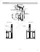
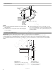
Product Dimensions Top trim widths: 30" (76.2 cm) 36" (91.4 cm) 13¹⁄₂" (34.3 cm) retractable vent height 1¹⁄₂" (3.8 cm) ³⁄₈" (0.95 cm) 27" (68.6 cm) for 30" (76.2 cm) vent 33" (83.8 cm) for 36" (91.4 cm) vent 5¹⁄₄"(13.3 cm) for 30" (76.2 cm) vent 8¹⁄₄"(21.0 cm) for 36" (91.4 cm) vent 28¹⁄₂" (72.4 cm) 13¹⁄₈" (33.4 cm) ³⁄₄ (1.9 cm) 16¹⁄₂" (42.0 cm) 10" (25.4 cm) 2¹⁄₈" (5.4 cm) Reversed Blower As-Received Blower Front of Range Hood Front of Range Hood 4³⁄₄" (12 cm) 10" (25.4 cm) 10" (25.
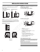
Cabinet Dimension 10" (25.4 cm) A= ¹⁄₂" (12.7 mm) minimum 21⁵⁄₁₆" (54.1 cm) 21⁵⁄₁₆" (54.1 cm) Cutouts are for 3¹⁄₄" x 10" (8.3 x 25.4 cm) rectangular or 6" (15.2 cm) round vent system. Locate power supply junction box at lower left hand rear corner of the cabinet. NOTES: ■ See cooktop manufacturer’s instructions for cooktop cutout depth and width. ■ Centerline of cooktop cutout ■ Use dimensions for vent system cutout location that applies to your installation.
Countertop Cutout Dimensions Chart Venting Requirements IMPORTANT: Make sure there is proper clearance within the wall or floor before making exhaust vent cutouts. ■ Use heavy (rigid) metal vent. B D C A A. ½" (12.7 mm) minimum to backsplash or rear wall B. ³⁄₄" (19.1 mm) maximum backsplash depth C. 27¹⁄₂" (69.9 cm) on 30" (76.2 cm) models 33¹⁄₂" (85.9 cm) on 36" (91.4 cm) models D. D = Measurement of cooktop rear overhang + 1¹³⁄₁₆" (46.
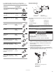
INSTALLATION INSTRUCTIONS Venting Methods Determine which venting method is best for your application. Vent system can terminate either through the wall or floor. Island Location - Vent System Installed Under a Concrete Slab Using PVC Sewer Pipe Island Location Front (Standard) Mounted Blower Motor Front (Standard)-Mounted Blower Motor Rear-Mounted Blower Motor B A D E C M F G A A H L K I J Rear Mounted Blower Motor A.
To calculate the length of the system you need, add the equivalent feet (meters) for each vent piece used in the system. Vent Piece Example Vent System C 3¹⁄₄" x 10" (8.3 cm x 25.4 cm) Rectangular B A 3¹⁄₄" x 10" (8.3 cm x 25.4 cm) 90° elbow 5.0 ft (1.5 m) 3¹⁄₄" x 10" (8.3 cm x 25.4 cm) flat elbow 12.0 ft (3.7 m) 3¹⁄₄" x 10" (8.3 cm x 25.4 cm) wall cap 0.0 ft (0.0 m) Vent Piece 6" (15.2 cm) Round 45° elbow 2.5 ft (0.8 m) 90° elbow 6 ft (1.8 m) 2 ft (0.6 m) D A. Blower motor B.
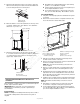
5. Attach the right and left end caps to the vent box. Place the tab into the mounting slot at each end of the downdraft vent as shown and push down to lock into place. ■ Downdraft vent is shipped with blower in down venting position so no modification is required. ■ If rear mounting of the blower motor is not required, go to the “Complete Installation” section. ■ To mount the blower motor to the rear side of the vent box, go to the “Rear Mounting - Blower Motor” section.
Rear Mounting - Blower Motor NOTE: Optional blower motor rear mounting position (opposite side) for island cabinet locations. The blower motor box assembly can be moved to the opposite side (rear) of the vent box. 1. Remove 7 screws from the mounting flanges of the blower motor box. 5. Remove the screws from the wire mounting plate. Front View A A A B C A. Screws B. Wire mounting plate C. Blower motor box A 6. Hold the wire mounting plate and push the grommet out of the mounting plate.
Complete Installation NOTE: The downdraft vent system is supplied with a 3¹⁄₄" x 10" (8.3 x 25.4 cm) back draft damper and a 6" (15.2 cm) round vent transition with damper. Refer to “3¹⁄₄" x 10" (8.3 x 25.4 cm) back draft damper” or “6" (15.2 cm) round vent transition with damper,” depending upon the type of venting you are using. 3¹⁄₄" x 10" (8.3 x 25.4 cm) Back Draft Damper 1. Attach the 3¼" x 10" (8.3 x 25.4 cm) back draft damper to the vent opening in the blower motor box, using three 3.5 x 9.
7. Fasten the lower support legs to the cabinet floor with screws (not provided). 4. Connect the 2 white wires together using UL listed wire connectors. F C D E A B A. Screw (not provided) 8. Tighten the lower support legs screws. Make Electrical Connections A A. Green or green and yellow ground wire B. White wires C. UL listed wire connectors WARNING D. Black wires E. UL listed or CSA approved conduit connector F. Downdraft vent wiring 5.
VENT SYSTEM USE The retractable downdraft vent system is designed to remove smoke, cooking vapors and odors from the cooktop area. ■ For best results, the vent should be operating before cooking is started. ■ If you use large or tall utensils, place them on the large rear element or burner surface. ■ A higher heat setting than normally used may be needed when the downdraft vent is operating. ■ For gas cooktops, the downdraft vent system may affect the flame stability and cooking performance.
WIRING DIAGRAM Y 7 Motor Specifications Power supply 120 VAC Frequency 60 Hz Wattage rating 420 W Amperage 3.7 A Motor Resistance BU/W 21.6 Ohms BU/R 18 Ohms BU/GY 14.3 Ohms BU/BK 9.8 Ohms Y/G S50 1˚ Speed W W 12 R W BR BR 7 5 3 8 6 1 BR 2˚ Speed R R 10 R W 4 GY 2 GY R 3˚ Speed GY GY BK BK W 4˚ Speed BK BK BU 1 BR BK R GY N.C. N.O. Com BR 1 11 Neutral BU GY R 8 1 N.C. N.O. Com R R 2 BU 9 9 BR N.O. Com BR N.C. 5 2 G W BK Y/G L N GY N.O.
ASSISTANCE OR SERVICE When calling for assistance or service, please know the purchase date and the complete model and serial number of your appliance. This information will help us to better respond to your request. If you need replacement parts If you need to order replacement parts, we recommend that you use only factory specified parts. Factory specified parts will fit right and work right because they are made with the same precision used to build every new appliance.
WHIRLPOOL CORPORATION MAJOR APPLIANCE WARRANTY LIMITED WARRANTY For one year from the date of purchase, when this major appliance is operated and maintained according to instructions attached to or furnished with the product, Whirlpool Corporation or Whirlpool Canada LP (hereafter “Whirlpool”) will pay for Factory Specified Parts and repair labor to correct defects in materials or workmanship. Service must be provided by a Whirlpool designated service company.
Notes www.goedekers.
SÉCURITÉ DU SYSTÈME DE VENTILATION Votre sécurité et celle des autres est très importante. Nous donnons de nombreux messages de sécurité importants dans ce manuel et sur votre appareil ménager. Assurez-vous de toujours lire tous les messages de sécurité et de vous y conformer. Voici le symbole d’alerte de sécurité. Ce symbole d’alerte de sécurité vous signale les dangers potentiels de décès et de blessures graves à vous et à d’autres.
IMPORTANTES INSTRUCTIONS DE SÉCURITÉ AVERTISSEMENT : POUR MINIMISER LE RISQUE AVERTISSEMENT : POUR RÉDUIRE LE RISQUE D'INCENDIE, CHOC ÉLECTRIQUE OU DOMMAGES CORPORELS, RESPECTER LES INSTRUCTIONS SUIVANTES : ■ Utiliser cet appareil uniquement dans les applications envisagées par le fabricant. Pour toute question, contacter le fabricant.
EXIGENCES D'INSTALLATION Outils et pièces Exigences d’emplacement Rassembler les outils et pièces nécessaires avant d’entreprendre l’installation. Lire et observer les instructions fournies avec chacun des outils de la liste ci-dessous. REMARQUE : Le système d’extraction par le bas est installé directement derrière la table de cuisson. Installer d’abord le système d’extraction par le bas, puis la table de cuisson. IMPORTANT : Observer les dispositions de tous les codes et règlements en vigueur.
Dimensions du produit Largeurs de la garniture supérieure : 30" (76,2 cm) 36" (91,4 cm) 13¹⁄₂" (34,3 cm) hauteur de l’évacuation rétractable 1¹⁄₂" (3,8 cm) ³⁄₈" (0,95 cm) 27" (68,6 cm) pour une évacuation de 30" (76,2 cm) 33" (83,8 cm) pour une évacuation de 36" (91,4 cm) 5¹⁄₄" (13,3 cm) pour une évacuation de 30" (76,2 cm) 8¹⁄₄"(21,0 cm) pour une évacuation de 36" (91,4 cm) 28¹⁄₂" (72,4 cm) 13¹⁄₈" (33,4 cm) ³⁄₄ (1,9 cm) 16¹⁄₂" (42,0 cm) 10" (25,4 cm) 2¹⁄₈" (5,4 cm) Ventilateur inversé Ventilateur mo
Dimensions du placard 10" (25,4 cm) A = ½" (12,7 mm) minimum 21 ⁵⁄₁₆" (54,1 cm) 21⁵⁄₁₆" (54,1 cm) Dimensions des ouvertures indiquées pour des conduits d'évacuation rectangulaire de 3¼" x 10" (8,3 x 25,4 cm) ou circulaire de 6" (15,2 cm). Axe central de l'ouverture recevant la table de cuisson Placer le boîtier de raccordement électrique dans l'angle arrière/ gauche au bas du placard.
Tableau des dimensions de l’ouverture du plan de travail Exigences concernant l'évacuation IMPORTANT : Avant d'effectuer des découpes, s'assurer qu'il y a un dégagement convenable dans le mur ou le plancher pour le système d’extraction. ■ Utiliser un conduit métallique rigide. B D C ■ Le système doit décharger l'air à l'extérieur. ■ Ne pas terminer le système d’extraction dans un grenier ou dans un autre espace fermé.
INSTRUCTIONS D'INSTALLATION Méthodes d’évacuation Déterminer la méthode d’évacuation la plus appropriée. La sortie à l’extérieur du circuit d’évacuation peut se faire à travers le plancher ou à travers un mur. Configuration en îlot Ventilateur monté à l’avant (standard) Ventilateur monté à l’arrière Configuration en îlot—Circuit d’évacuation installé sous une dalle de béton (utilisation de conduit de PVC pour égout) Ventilateur monté à l’avant (standard) B A D H L K A.
Exemple de circuit d’évacuation Calcul de la longueur effective du circuit d’évacuation C Un conduit rectangulaire de 3¼" x 10" (8,3 x 25,4 cm) est nécessaire pour la caisse du ventilateur. Il peut être raccordé à un conduit rond de 6" (15,2 cm) si nécessaire. 6 pi (1,8 m) B A Longueur maximum du circuit d’évacuation Conduit d’évacuation Longueur Conduit dia.
5. Fixer les embouts à droite et à gauche sur la caisse du système d’extraction. Placer la languette dans la rainure de montage à chaque extrémité de la caisse du système d’extraction par le bas comme illustré et l’emboîter en la poussant vers le bas. A B Évacuation par le bas : REMARQUE : Si le clapet anti-retour est monté vers le bas, une bouche de décharge murale ou à travers le toit équipée d’un clapet est nécessaire à l’extrémité du circuit d’évacuation.
Montage du ventilateur à l'arrière REMARQUE : Position de montage du ventilateur à l’arrière (côté opposé) possible pour les configurations en îlot. On peut déplacer la caisse du moteur du ventilateur du côté opposé (arrière) de la caisse du système d’extraction. 1. Ôter les 7 vis des rebords de montage de la caisse du ventilateur. 5. Retirer les vis de la platine de montage du câble. Vue de face A A A B C A. Vis B. Platine de montage du câble C. Caisse du ventilateur 6.
Achever l’installation REMARQUE : Le système d’extraction par le bas est livré avec un clapet anti-retour de 3¹⁄₄" x 10" (8,3 x 25,4 cm) et un raccord de transition pour conduit rond de 6" (15,2 cm) avec clapet. Se reporter à la section “Clapet anti-retour de 3¹⁄₄" x 10" (8,3 x 25,4 cm)” ou “Raccord de transition pour conduit rond de 6" (15,2 cm) avec clapet”, selon le type de circuit d’évacuation utilisé. 2. Ôter les 4 vis du couvercle du boîtier de connexion.
5. Percer 2 avant-trous à travers les équerres de fixation sous le plan de travail, dans la face inférieure du plan de travail. Avec 2 vis (non fournies) de la longueur adéquate, fixer les équerres au plan de travail. IMPORTANT : Choisir des vis d’une longueur adéquate pour ne pas traverser le plan de travail au serrage. AVERTISSEMENT B C Risque de choc électrique Relier le ventilateur à la terre. Brancher le fil relié à la terre au fil vert et jaune relié à la terre dans la boîte de la borne.
Contrôle du fonctionnement 1. Appuyer pendant quelques secondes sur le bouton au sommet du système d’extraction par le bas. La partie rétractable du système d’extraction par le bas se soulève, et le ventilateur se met en marche. Positionner la garniture supérieure sur la section rétractable; emboîter la garniture en place. On peut trouver chez le revendeur local des ensembles de garniture assortis à la couleur de la table de cuisson.
ENTRETIEN DU SYSTÈME D’ÉVACUATION Nettoyage : Surface du système d’extraction par le bas Pour éviter d’endommager la finition, nettoyer les surfaces avec de l’eau savonneuse. Ne pas utiliser une solution de récurage ou un produit abrasif. Surfaces externes : Afin d’éviter d’endommager la surface externe, ne pas utiliser de tampons en laine d’acier ou de tampons à récurer savonneux. Toujours essuyer pour éviter de laisser des marques d’eau.
SCHÉMA DE CÂBLAGE 7 Caractéristiques du moteur Alimentation 120 VCA Fréquence 60 Hz Puissance nominale 420 W Intensité 3,7 A Résistance du moteur BU/BL 21,6 ohms BU/R 18 ohms BU/GRIS 14,3 ohms BU/N 9,8 ohms JA/VE S50 BL MAR MAR GRIS MAR R N.O. Com MAR 5 N.F. 2 BL N N.O. Com R BU MAR GRIS 1 N.F. GRIS 3 N.O. Com N.F.
ASSISTANCE OU SERVICE Lors d’un appel pour assistance ou service, veuillez connaître la date d’achat, le numéro de modèle et le numéro de série complets de l’appareil. Ces renseignements nous aideront à mieux répondre à votre demande. Si vous avez besoin de pièces de rechange Si vous avez besoin de commander des pièces de rechange, nous vous recommandons d’employer uniquement les pièces spécifiées par l’usine.
GARANTIE DES GROS APPAREILS MÉNAGERS WHIRLPOOL CORPORATION GARANTIE LIMITÉE Pendant un an à compter de la date d'achat, lorsque ce gros appareil ménager est utilisé et entretenu conformément aux instructions jointes à ou fournies avec le produit, Whirlpool Corporation ou Whirlpool Canada LP (ci-après désignées “Whirlpool”) paiera pour les pièces spécifiées par l'usine et la main-d'œuvre pour corriger les vices de matériaux ou de fabrication.
W10342491D © 2012 Whirlpool Corporation. All rights reserved. Used under license in Canada. Tous droits réservés. Utilisée sous licence au Canada. 10/12 Printed in Mexico Imprimé au Mexique www.goedekers.