30" (76.2 CM) RANGE HOOD Installation Instructions and Use & Care Guide For questions about features, operation/performance, parts, accessories or service, call: 1-800-253-1301 or visit our website at www.whirlpool.com In Canada, call 1-800-807-6777 or visit our website at www.whirlpool.ca HOTTE D’ASPIRATION DE 30" (76,2 CM) Instructions d’installation et Guide d’utilisation et d’entretien Au Canada, pour assistance, installation ou service, composer le 1-800-807-6777 ou visiter notre site Web à www.
TABLE OF CONTENTS RANGE HOOD SAFETY..................................................................2 INSTALLATION REQUIREMENTS..................................................4 Tools and Parts..............................................................................4 Location Requirements.................................................................4 Venting System.............................................................................5 Electrical Requirements................................
State of California Proposition 65 Warnings: WARNING: This product contains one or more chemicals known to the State of California to cause cancer. WARNING: This product contains one or more chemicals known to the State of California to cause birth defects or other reproductive harm.
INSTALLATION REQUIREMENTS Tools and Parts Optional accessories Gather the required tools and parts before starting installation. Read and follow the instructions provided with any tools listed here. Power cord kit Part Number W10355452* Tools needed Metal snips Wire stripper #2 Phillips screwdriver Flat-blade screwdriver Pencil Drill with ¹⁄₈" (3 mm), ¹⁄₂" (13 mm) and 1¹⁄₄" (3 cm) bits * For information on ordering, see the “Assistance or Service” section.
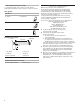
Top Venting Installation Clearances Wall Venting B A A B C A D B A. 7" (17.8 cm) round vent through roof (purchased separately) B. Roof cap with damper (purchased separately) A. 7" (17.8 cm) round vent out the top and through the wall (purchased separately) B.
Calculating Vent System Length To calculate the length of the system you need, add the equivalent feet (meters) for each vent piece used in the system. Vent System Vent Piece 45° elbow 2.5 ft (0.8 m) 90° elbow 5 ft (1.5 m) 7" (17.8 cm) wall cap 0 ft (0 m) Electrical Requirements Observe all governing codes and ordinances. Ensure that the electrical installation is adequate and in conformance with National Electrical Code, ANSI/NFPA 70 (latest edition) or CSA Standards C22.
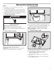
INSTALLATION INSTRUCTIONS NOTES: ■■ Depending on your model, determine which venting method to use: roof or wall. ■■ It is recommended that the vent system be installed before the range hood is installed. Go to “Venting System” in the “Installation Requirements” section if you need assistance. ■■ Before making cutouts, make sure there is proper clearance within the ceiling or wall for the vent system. 3. Install Brackets 1.
5. Mark Hole Locations 6. Mark and Cut Vent Opening 7" (17.8 cm) Round Vent System 1" (2.5 cm) A ■■ Lift the range hood into place and insert the mounting bracket tabs through the slots in the back of the range hood. Using the 7" (17.8 cm) round vent mounting plate, draw the vent opening outline on the underside of the cabinet: -- Place the vent mounting plate on the bottom of the cabinet.
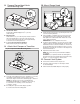
8. Prepare Range Hood Vents and Mounting Tabs x2 B 10. Mount Range Hood D C A ■■ Install Strain Relief Install a UL Listed/CSA Approved 1/2" (13 mm) strain relief (A). ■■ Mounting Tabs Start a #8-18 x 5/8" (4.2 x 16 mm) truss-head screw into the mounting tab (D) on each side of the range hood as shown in the inset. Insert the screws approximately 2 turns into the mounting tab holes. ■■ 7" (17.8 cm) Round Vent Installations Remove both top knockouts (B and C).
12. Make Electrical Connection A B C 13. Complete the Installation ■■ Install a 120V, 75W maximum, light bulb with E26 base. See “Replacing the Light Bulb” in the “Range Hood Care” section. ■■ If removed previously, replace the filter. See “Metal Grease Filter” in the “Range Hood Care” section. Check the operation of the range hood fan and light. See the “Range Hood Use” section. If the range hood does not operate, check to see whether a circuit breaker has tripped or a household fuse has blown.
RANGE HOOD CARE Cleaning IMPORTANT: Clean the hood and grease filters frequently according to the following instructions. Replace the grease filter before operating hood. Exterior Surfaces IMPORTANT: Do not use soap-filled scouring pads, abrasive cleaners, cooktop polishing creme, steel wool, gritty washcloths, or paper towels. To avoid damage to the stainless steel, do not use cleaners that contain chlorine.
WIRING DIAGRAM SE116C Light Switch On - Off BK Motor Switch Low - Off - High BK Brown - Red 12 9.36 ±10% Ohms N C19 RD BK BK Speed 1 Common WH RD BR WH Motor Characteristics Power Supply 120 VAC Frequency 60 Hz Amperage 0.65 ±10% A Wattage Rating 38 ±10% Watts Motor Resistance 16.
ASSISTANCE OR SERVICE If you need service In Canada Please refer to the warranty page in this manual. If you need replacement parts If you need to order replacement parts, we recommend that you use only factory specified parts. Factory specified parts will fit right and work right because they are made with the same precision used to build every new appliance.
WHIRLPOOL® MAJOR APPLIANCE LIMITED WARRANTY ATTACH YOUR RECEIPT HERE. PROOF OF PURCHASE IS REQUIRED TO OBTAIN WARRANTY SERVICE. Please have the following information available when you call the Customer eXperience Center: ■■ Name, address and telephone number ■■ Model number and serial number ■■ A clear, detailed description of the problem ■■ Proof of purchase including dealer or retailer name and address IF YOU NEED SERVICE: 1.
SÉCURITÉ DE LA HOTTE DE CUISINIÈRE Votre sécurité et celle des autres est très importante. Nous donnons de nombreux messages de sécurité importants dans ce manuel et sur votre appareil ménager. Assurez-vous de toujours lire tous les messages de sécurité et de vous y conformer. Voici le symbole d’alerte de sécurité. Ce symbole d’alerte de sécurité vous signale les dangers potentiels de décès et de blessures graves à vous et à d’autres.
IMPORTANTES INSTRUCTIONS DE SÉCURITÉ AVERTISSEMENT : POUR RÉDUIRE LE RISQUE D'INCENDIE, CHOC ÉLECTRIQUE OU DOMMAGES CORPORELS, RESPECTER LES INSTRUCTIONS SUIVANTES : ■ Utiliser cet appareil uniquement dans les applications envisagées par le fabricant. Pour toute question, contacter le fabricant.
EXIGENCES D’INSTALLATION Outillage et pièces Accessoires en option Rassembler les outils et pièces nécessaires avant d’entreprendre l’installation. Lire et observer les instructions fournies avec chacun des outils de la liste ci-dessous.
Dimensions du produit Circuit d’évacuation 6⁹⁄₁₆" (16,7 cm) 2" (5,1 cm) Méthodes d’évacuation 1" (2,5 cm) 4¹⁵⁄₁₆" (12,5 cm) 1" (2,5 cm) 9" (22,9 cm) 29¹⁵⁄₁₆" (76,0 cm) 1¹⁄₂" (3,8 cm) 18⁵⁄₈" (47,3 cm) REMARQUES : ■■ L’emploi d’un conduit flexible est déconseillé. Un conduit flexible peut causer une rétro-pression et des turbulences de l’air, ce qui réduit considérablement la performance. Le circuit d’évacuation est facultatif pour ce modèle.
Exigences concernant l’évacuation ■■ Le système doit décharger l’air à l’extérieur. ■■ Ne pas terminer le circuit d’évacuation dans un grenier ou dans un autre espace clos. ■■ Ne pas utiliser une bouche de décharge murale de 4" (10,2 cm) normalement utilisée pour un équipement de buanderie. ■■ Utiliser un conduit d’évacuation métallique circulaire de 7" (17,8 cm). Un conduit en métal rigide est recommandé. Ne pas utiliser de conduit de plastique ou en aluminium.
REMARQUES : INSTRUCTIONS D’INSTALLATION ■■ Selon le modèle, déterminer la méthode d’évacuation à utiliser : à travers le toit ou à travers le mur. ■■ Il est recommandé que l’installation du circuit d’évacuation soit réalisée avant celle de la hotte. Voir “Circuit d’évacuation” dans la section “Exigences d’installation” en cas de besoin. ■■ Avant d’exécuter les découpages, vérifier qu’il existe un dégagement suffisant dans le plafond ou le mur pour le conduit d’évacuation. 3.
5. Marquage de l’emplacement des trous 6. Marquage et découpage de l’ouverture d’évacuation Circuit d’évacuation pour conduit circulaire de 7" (17,8 cm) 1" (2.5 cm) A ■■ Remettre la hotte en place et insérer les pattes des brides de montage dans les fentes situées à l’arrière de la hotte.
8. Préparation des conduits d’évacuation et des pattes de montage de la hotte x2 B 10. Montage de la hotte D C A ■■ Installation du serre-câble Installer un serre-câble de 1/2" (13 mm) homologué UL/CSA (A). ■■ Pattes de montage Engager des vis à tête bombée n° 8-18 x 5/8" (4,2 x 16 mm) dans les pattes de montage (D) de chaque côté de la hotte comme illustré. Faire tourner les vis sur environ 2 tours à travers les trous des pattes de montage.
12. Raccordement électrique A B C Option 1 - Installations avec raccordement par câblage direct ■■ Connecter ensemble les 3 conducteurs blancs (A) à l’aide d’un connecteur de fils homologué UL/CSA. ■■ Connecter ensemble les 2 conducteurs noirs (B) à l’aide d’un connecteur de fils homologué UL/CSA. AVERTISSEMENT 13. Achever l’installation ■■ Installer une ampoule de 75 watts maximum, 120 V, à culot E26. Voir “Remplacement de l’ampoule” dans la section “Entretien de la hotte”.
ENTRETIEN DE LA HOTTE Nettoyage IMPORTANT : Nettoyer fréquemment la hotte et les filtres à graisse en suivant les instructions suivantes. Réinstaller le filtre à graisse avant de faire fonctionner la hotte. Surfaces externes IMPORTANT : Ne pas utiliser de tampons de récurage savonneux, de nettoyants abrasifs, de crème à polir pour table de cuisson, de laine d’acier, de chiffons de lavage rugueux ou d’essuie-tout.
SCHÉMA DE CÂBLAGE SE116C Commutateur d’eclairage Marche - Arrêt Marron - Rouge 9,36 ±10% Ohms Neu C19 N Vitesse 1 Commun BL R MAR BL Caractéristiques du moteur Alimentation électrique 120 VCA Fréquence 60 Hz Intensité 0,65 ±10% A Puissance nominale 38 ±10% Watts Résistance du moteur Marron - Blanc 16,98 ±10% Ohms BL Vitesse 2 BL R MAR BL R N N N Contacteur du moteur Faible - Arrêt - Élevé Ph Vis de mise à la terre Terre 25
ASSISTANCE OU SERVICE Si vous avez besoin de service ■■ Caractéristiques et spécifications sur toute notre gamme d’appareils électroménagers. ■■ Références aux marchands locaux. ■■ Consignes d’utilisation et d’entretien. ■■ Vente d’accessoires et de pièces de rechange. ■■ Orientation vers des concessionnaires, distributeurs de pièces de rechange et services de réparation locaux.
GARANTIE LIMITÉE DES GROS APPAREILS MÉNAGERS WHIRLPOOL® ATTACHEZ ICI VOTRE REÇU DE VENTE. UNE PREUVE D’ACHAT EST OBLIGATOIRE POUR OBTENIR L’APPLICATION DE LA GARANTIE.
CLAUSE D’EXONÉRATION DE RESPONSABILITÉ AU TITRE DES GARANTIES IMPLICITES LES GARANTIES IMPLICITES, Y COMPRIS LES GARANTIES APPLICABLES DE QUALITÉ MARCHANDE OU D’APTITUDE À UN USAGE PARTICULIER, SONT LIMITÉES À UN AN OU À LA PLUS COURTE PÉRIODE AUTORISÉE PAR LA LOI. Certains États et provinces ne permettent pas de limitation sur la durée des garanties implicites de qualité marchande ou d’aptitude à un usage particulier, de sorte que la limitation ci-dessus peut ne pas être applicable dans votre cas.