30" (76.2 CM) AND 36" (91.4 CM) RANGE HOOD Installation Instructions and Use & Care Guide For questions about features, operation/performance, parts, accessories or service, call: 1-800-253-1301 or visit our website at www.whirlpool.com In Canada, call 1-800-807-6777 or visit our website at www.whirlpool.
TABLE OF CONTENTS TABLE DES MATIÈRES RANGE HOOD SAFETY .................................................................2 INSTALLATION REQUIREMENTS ................................................4 Tools and Parts ............................................................................4 Location Requirements................................................................4 Venting Requirements..................................................................5 Electrical Requirements ...................
IMPORTANT SAFETY INSTRUCTIONS WARNING: TO REDUCE THE RISK OF FIRE, ELECTRIC SHOCK, OR INJURY TO PERSONS, OBSERVE THE FOLLOWING: ■ Use this unit only in the manner intended by the manufacturer. If you have questions, contact the manufacturer. ■ Before servicing or cleaning the unit, switch power off at service panel and lock the service disconnecting means to prevent power from being switched on accidentally.
INSTALLATION REQUIREMENTS Tools and Parts Gather the required tools and parts before starting installation. Read and follow the instructions provided with any tools listed here. Tools needed ■ Drill ■ 1¹⁄₄" (3.0 cm) drill bit ■ ¹⁄₈" (3.
For the most efficient and quiet operation: ■ Use no more than three 90° elbows. Installation Clearances ■ Make sure there is a minimum of 24" (61 cm) of straight vent between the elbows if more than 1 elbow is used. ■ Do not install 2 elbows together. ■ Use clamps or duct tape to seal all joints in the vent system. ■ The vent system must have a damper. If roof or wall cap has a damper, remove the damper flap from the vent damper supplied with the range hood.
Calculating Vent System Length Electrical Requirements To calculate the length of the system you need, add the equivalent feet (meters) for each vent piece used in the system. 3¹⁄₄" x 10" (8.3 cm x 25.4 cm) Vent System Vent Piece 3¹⁄₄" x 10" (8.3 cm x 25.4 cm) 90° elbow 5.0 ft (1.5 m) 3¹⁄₄" x 10" (8.3 cm x 25.4 cm) flat elbow 12.0 ft (3.7 m) 3¹⁄₄" x 10" (8.3 cm x 25.4 cm) wall cap 0.0 ft (0.0 m) Observe all governing codes and ordinances.
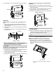
INSTALLATION INSTRUCTIONS Prepare Location NOTE: It is recommended that the vent system be installed before hood is installed. Before making cutouts, make sure there is proper clearance within the ceiling or wall for exhaust vent. 1. Disconnect power. 2. Depending on your model, determine which venting method to use: roof or wall. 3. Select a flat surface for assembling the range hood. Place covering over that surface. 4. Lift the range hood and set it upside down onto covered surface. 5.
4. Repeat steps 1-3 for the underside of the top of the cabinet. Cabinet cutouts To make a circular vent opening on the underside of the cabinet top: 1. Mark a centerline on the underside of the top of cabinet. 2. Mark a line 5" (12.7 cm) from the back wall on the underside of the top of cabinet. 3. Use a compass or a circle template to draw a circle with a diameter that is ¼" (0.64 cm) larger than the vent. 4. Use saber or keyhole saw to cut the circular vent opening. *¹⁄₂" (1.
2. Lift the range hood up under cabinet and determine final location by centering beneath cabinet. Mark on the underside of cabinet the location of the 4 keyhole mounting slots on the range hood. Set range hood aside on a covered surface. A 6. Install the 3¼" x 10" (8.3 x 25.4 cm) vent damper. Attach to range hood with the 3.5 x 9.5 mm screws provided and remove tape from damper flap. NOTE: The 3¹⁄₄" x 10" (8.3 x 25.4 cm) rectangular vent damper can be installed up to 1" (2.
Power Supply Cable Installation Make Electrical Connection 1. For direct wire installations, run the home power supply cable according to the National Electric Code or CSA standards and local codes and ordinances. There must be enough wiring from the fused disconnect (or circuit breaker) box to make the connection in the hood electrical terminal box. For optional power supply cord kit installations, follow the instructions in the “Make Electrical Connection” section.
Complete Installation 1. Install the 75W (max.) Incandescent light bulb. See “Replacing the Incandescent Light Bulb” in the “Range Hood Care” section. 2. Replace grease filter if removed. See the “Range Hood Care” section. 3. Check the operation of the range hood fan and light. See “Range Hood Use” section. If range hood does not operate, check to see whether a circuit breaker has tripped or a household fuse has blown. Disconnect power and check wiring connections.
Replacing the Incandescent Light Bulb Turn off the range hood and allow the light bulb to cool. 1. Disconnect power. 2. Squeeze the plastic lens cover and remove it from the hood. A 3. Screw light bulb into socket. 4. Replace lens cover by squeezing cover and inserting tabs into slots. 5. Reconnect power. If new light does not operate, make sure the lamp is inserted correctly before calling service. B A. Light bulb socket B.
ASSISTANCE OR SERVICE If you need service In Canada Please refer to the warranty page in this manual. If you need replacement parts If you need to order replacement parts, we recommend that you use only factory specified parts. Factory specified parts will fit right and work right because they are made with the same precision used to build every new appliance.
® WHIRLPOOL MAJOR APPLIANCE LIMITED WARRANTY ATTACH YOUR RECEIPT HERE. PROOF OF PURCHASE IS REQUIRED TO OBTAIN WARRANTY SERVICE. Please have the following information available when you call the Customer eXperience Center: ■ Name, address and telephone number ■ Model number and serial number ■ A clear, detailed description of the problem ■ Proof of purchase including dealer or retailer name and address IF YOU NEED SERVICE: 1.
SÉCURITÉ DE LA HOTTE DE CUISINIÈRE Votre sécurité et celle des autres est très importante. Nous donnons de nombreux messages de sécurité importants dans ce manuel et sur votre appareil ménager. Assurez-vous de toujours lire tous les messages de sécurité et de vous y conformer. Voici le symbole d’alerte de sécurité. Ce symbole d’alerte de sécurité vous signale les dangers potentiels de décès et de blessures graves à vous et à d’autres.
IMPORTANTES INSTRUCTIONS DE SÉCURITÉ AVERTISSEMENT : POUR RÉDUIRE LE RISQUE D'INCENDIE, CHOC ÉLECTRIQUE OU DOMMAGES CORPORELS, RESPECTER LES INSTRUCTIONS SUIVANTES : ■ Utiliser cet appareil uniquement dans les applications envisagées par le fabricant. Pour toute question, contacter le fabricant.
EXIGENCES D'INSTALLATION Outils et pièces Exigences d'emplacement Rassembler les outils et pièces nécessaires avant d’entreprendre l’installation. Lire et observer les instructions fournies avec chacun des outils de la liste ci-dessous. IMPORTANT : Observer les dispositions de tous les codes et règlements en vigueur. ■ C’est à l’installateur qu’incombe la responsabilité de respecter les distances de séparation exigées, spécifiées sur la plaque signalétique de l’appareil.
■ Distances de dégagement à respecter Le circuit d’évacuation doit comporter un clapet anti-reflux. Si la bouche de décharge murale ou par le toit comporte un clapet anti-reflux, retirer le volet du clapet anti-reflux fourni avec la hotte de cuisinière. (Voir “Dépose du volet du clapet anti-retour sur le raccord de conduit de 3¼" x 10" [8,3 x 25,4 cm]” dans la section “Installation de la cuisinière”.
Calcul de la longueur du circuit d’évacuation Pour calculer la longueur effective du circuit d’évacuation nécessaire, additionner les longueurs équivalentes (en pieds ou mètres) de tous les composants utilisés dans le système.
INSTRUCTIONS D’INSTALLATION Préparation de l'emplacement REMARQUE : Il est recommandé d'installer le système d'évacuation avant de procéder à l'installation de la hotte. Avant d’exécuter les découpages, vérifier la disponibilité d’un dégagement suffisant dans le plafond ou le mur pour le conduit d’évacuation. 1. Déconnecter la source de courant électrique. 2. Selon le modèle, déterminer la méthode d’évacuation à utiliser : décharge à travers le mur ou le toit. 3.
4. Répéter les étapes 1 à 3 pour la face inférieure du sommet du placard. 3. Utiliser une scie sauteuse ou une scie à guichet pour découper l'ouverture rectangulaire pour le passage du conduit d'évacuation.
Installation de la hotte REMARQUE : Votre modèle comporte un clapet anti-reflux rectangulaire de 3¹⁄₄" x 10" (8,3 x 25,4 cm) à l'intérieur de la hotte. 1. Retirer le clapet anti-reflux rectangulaire de 3¹⁄₄" x 10" (8,3 x 25,4 cm) fixé avec des vis de 3,5 x 9,5 mm à l'intérieur de la hotte. Utiliser ces vis pour installer le clapet anti-reflux rectangulaire. 4. Installer les 4 vis de montage 4,5 x 13 mm dans les avanttrous.
Dépose du volet du clapet anti-retour sur le raccord de conduit de 3¼" x 10" (8,3 x 25,4 cm) 1. Dégager la tige de retenue de la languette de fixation située sur le volet du clapet anti-retour. C D B A H G F A. Tige de retenue B. Guide de la tige du volet du clapet anti-retour C. Embouts en plastique D. Languettes de butée Installation du cordon d'alimentation 1.
Raccordement électrique AVERTISSEMENT AVERTISSEMENT Risque d'incendie Relier le ventilateur à la terre. Risque de choc électrique Utiliser du fil en cuivre. Déconnecter la source de courant électrique avant l'entretien. Brancher le fil relié à la terre à la vis verte reliée à la terre dans la boîte de la borne. Replacer pièces et panneaux avant de faire la remise en marche. Le non-respect de ces instructions peut causer un décès, un incendie ou un choc électrique.
UTILISATION DE LA HOTTE La hotte de cuisinière est conçue pour extraire fumée, vapeurs de cuisson et odeurs de la zone de la table de cuisson. Pour obtenir les meilleurs résultats, mettre le ventilateur de la hotte en marche avant d’entreprendre une cuisson, et laisser le ventilateur fonctionner pendant plusieurs minutes après l’achèvement d’une cuisson pour pouvoir évacuer de la cuisine toute trace d’odeur de cuisson, vapeur ou fumée. Les commandes de la hotte sont situées sur le sommet de la hotte.
3. Visser la lampe dans la douille. 4. Réinstaller le cabochon : exercer une pression sur le cabochon pour pouvoir insérer les pattes dans les ouvertures d’insertion. 5. Reconnecter la source de courant électrique. Si la nouvelle lampe ne fonctionne pas, vérifier que chaque lampe est correctement insérée dans sa douille avant de demander l’intervention d’un dépanneur. Remplacement de l'ampoule à incandescence Éteindre la hotte et laisser l'ampoule refroidir. 1. Déconnecter la source de courant électrique.
ASSISTANCE OU SERVICE Si vous avez besoin de service Pour plus d’assistance Consulter la page de garantie du présent manuel. Si vous avez besoin de plus d’assistance, vous pouvez soumettre par écrit toute question ou préoccupation à Whirlpool Canada à l’adresse suivante : Whirlpool Brand Home Appliances Centre pour l’eXpérience de la clientèle Whirlpool Canada 200 - 6750 Century Ave.
GARANTIE LIMITÉE DES GROS APPAREILS MÉNAGERS WHIRLPOOL® ATTACHEZ ICI VOTRE REÇU DE VENTE. UNE PREUVE D’ACHAT EST OBLIGATOIRE POUR OBTENIR L'APPLICATION DE LA GARANTIE.