30" (76.2 CM) AND 36" (91.4 CM) RANGE HOOD Installation Instructions and Use & Care Guide For questions about features, operation/performance, parts, accessories or service, call: 1-800-253-1301 or visit our website at www.whirlpool.com In Canada, call 1-800-807-6777 or visit our website at www.whirlpool.
TABLE OF CONTENTS TABLE DES MATIÈRES RANGE HOOD SAFETY .................................................................2 INSTALLATION REQUIREMENTS ................................................4 Tools and Parts ............................................................................4 Location Requirements ................................................................4 Venting Requirements..................................................................5 Electrical Requirements ..................
IMPORTANT SAFETY INSTRUCTIONS WARNING: TO REDUCE THE RISK OF FIRE, ELECTRIC SHOCK, OR INJURY TO PERSONS, OBSERVE THE FOLLOWING: ■ Use this unit only in the manner intended by the manufacturer. If you have questions, contact the manufacturer. ■ Before servicing or cleaning the unit, switch power off at service panel and lock the service disconnecting means to prevent power from being switched on accidentally.
INSTALLATION REQUIREMENTS Tools and Parts Gather the required tools and parts before starting installation. Read and follow the instructions provided with any tools listed here. Tools needed ■ Drill ■ 1¹⁄₄" (3.0 cm) drill bit ■ ¹⁄₈" (3.
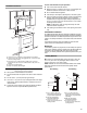
For the most efficient and quiet operation: Use no more than three 90° elbows. Installation Clearances ■ ■ Make sure there is a minimum of 24" (61 cm) of straight vent between the elbows if more than 1 elbow is used. ■ Do not install 2 elbows together. ■ Use clamps or duct tape to seal all joints in the vent system. ■ The vent system must have a damper. If roof or wall cap has a damper, remove the damper flap from the vent damper supplied with the range hood.
Calculating Vent System Length Electrical Requirements To calculate the length of the system you need, add the equivalent feet (meters) for each vent piece used in the system. 3¹⁄₄" x 10" (8.3 cm x 25.4 cm) Vent System Vent Piece 3¹⁄₄" x 10" (8.3 cm x 25.4 cm) 90° elbow 5.0 ft (1.5 m) 3¹⁄₄" x 10" (8.3 cm x 25.4 cm) flat elbow 12.0 ft (3.7 m) 3¹⁄₄" x 10" (8.3 cm x 25.4 cm) wall cap 0.0 ft (0.0 m) Observe all governing codes and ordinances.
INSTALLATION INSTRUCTIONS Prepare Location NOTE: It is recommended that the vent system be installed before hood is installed. Before making cutouts, make sure there is proper clearance within the ceiling or wall for exhaust vent. 1. Disconnect power. 2. Depending on your model, determine which venting method to use: roof or wall. 3. Select a flat surface for assembling the range hood. Place covering over that surface. 4. Lift the range hood and set it upside down onto covered surface. 5.
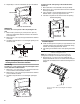
4. Repeat steps 1-3 for the underside of the top of the cabinet. Cabinet cutouts *¹⁄₂" (1.3 cm) To make a circular vent opening on the underside of the cabinet top: 1. Mark a centerline on the underside of the top of cabinet. 2. Mark a line 5" (12.7 cm) from the back wall on the underside of the top of cabinet. 3. Use a compass or a circle template to draw a circle with a diameter that is ¼" (0.64 cm) larger than the vent. 4. Use saber or keyhole saw to cut the circular vent opening.
2. Lift the range hood up under cabinet and determine final location by centering beneath cabinet. Mark on the underside of cabinet the location of the 4 keyhole mounting slots on the range hood. Set range hood aside on a covered surface. A 6. Install the 3¼" x 10" (8.3 x 25.4 cm) vent damper. Attach to range hood with the 3.5 x 9.5 mm screws provided and remove tape from damper flap. NOTE: The 3¹⁄₄" x 10" (8.3 x 25.4 cm) rectangular vent damper can be installed up to 1" (2.
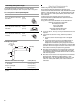
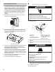
Power Supply Cable Installation Make Electrical Connection 1. For direct wire installations, run the home power supply cable according to the National Electric Code or CSA standards and local codes and ordinances. There must be enough wiring from the fused disconnect (or circuit breaker) box to make the connection in the hood electrical terminal box. For optional power supply cord kit installations, follow the instructions in the “Make Electrical Connection” section.
Complete Installation 1. Install the 75W (max.) Incandescent light bulb. See “Replacing the Incandescent Light Bulb” in the “Range Hood Care” section. 2. Replace grease filter if removed. See the “Range Hood Care” section. 3. Check the operation of the range hood fan and light. See “Range Hood Use” section. If range hood does not operate, check to see whether a circuit breaker has tripped or a household fuse has blown. Disconnect power and check wiring connections.
Replacing the Incandescent Light Bulb Turn off the range hood and allow the light bulb to cool. 1. Disconnect power. 2. Squeeze the plastic lens cover and remove it from the hood. B A 3. Screw light bulb into socket. 4. Replace lens cover by squeezing cover and inserting tabs into slots. 5. Reconnect power. If new light does not operate, make sure the lamp is inserted correctly before calling service. A. Light bulb socket B.
ASSISTANCE OR SERVICE When calling for assistance or service, please know the purchase date and the complete model and serial number of your appliance. This information will help us to better respond to your request. If you need replacement parts If you need to order replacement parts, we recommend that you use only factory specified parts. Factory specified parts will fit right and work right because they are made with the same precision used to build every new appliance.
WHIRLPOOL CORPORATION MAJOR APPLIANCE WARRANTY LIMITED WARRANTY For one year from the date of purchase, when this major appliance is operated and maintained according to instructions attached to or furnished with the product, Whirlpool Corporation or Whirlpool Canada LP (hereafter “Whirlpool”) will pay for Factory Specified Parts and repair labor to correct defects in materials or workmanship. Service must be provided by a Whirlpool designated service company.
SÉCURITÉ DE LA HOTTE DE CUISINIÈRE Votre sécurité et celle des autres est très importante. Nous donnons de nombreux messages de sécurité importants dans ce manuel et sur votre appareil ménager. Assurez-vous de toujours lire tous les messages de sécurité et de vous y conformer. Voici le symbole d’alerte de sécurité. Ce symbole d’alerte de sécurité vous signale les dangers potentiels de décès et de blessures graves à vous et à d’autres.
IMPORTANTES INSTRUCTIONS DE SÉCURITÉ AVERTISSEMENT : POUR RÉDUIRE LE RISQUE D'INCENDIE, CHOC ÉLECTRIQUE OU DOMMAGES CORPORELS, RESPECTER LES INSTRUCTIONS SUIVANTES : ■ Utiliser cet appareil uniquement dans les applications envisagées par le fabricant. Pour toute question, contacter le fabricant.
EXIGENCES D'INSTALLATION Outils et pièces Exigences d'emplacement Rassembler les outils et pièces nécessaires avant d’entreprendre l’installation. Lire et observer les instructions fournies avec chacun des outils de la liste ci-dessous. IMPORTANT : Observer les dispositions de tous les codes et règlements en vigueur. ■ C’est à l’installateur qu’incombe la responsabilité de respecter les distances de séparation exigées, spécifiées sur la plaque signalétique de l’appareil.
■ Distances de dégagement à respecter Le circuit d’évacuation doit comporter un clapet anti-reflux. Si la bouche de décharge murale ou par le toit comporte un clapet anti-reflux, retirer le volet du clapet anti-reflux fourni avec la hotte de cuisinière. (Voir “Dépose du volet du clapet anti-retour sur le raccord de conduit de 3¼" x 10" [8,3 x 25,4 cm]” dans la section “Installation de la cuisinière”.
Calcul de la longueur du circuit d’évacuation Pour calculer la longueur effective du circuit d’évacuation nécessaire, additionner les longueurs équivalentes (en pieds ou mètres) de tous les composants utilisés dans le système.
INSTRUCTIONS D’INSTALLATION Préparation de l'emplacement REMARQUE : Il est recommandé d'installer le système d'évacuation avant de procéder à l'installation de la hotte. Avant d’exécuter les découpages, vérifier la disponibilité d’un dégagement suffisant dans le plafond ou le mur pour le conduit d’évacuation. 1. Déconnecter la source de courant électrique. 2. Selon le modèle, déterminer la méthode d’évacuation à utiliser : décharge à travers le mur ou le toit. 3.
4. Répéter les étapes 1 à 3 pour la face inférieure du sommet du placard. 3. Utiliser une scie sauteuse ou une scie à guichet pour découper l'ouverture rectangulaire pour le passage du conduit d'évacuation.
Installation de la hotte REMARQUE : Votre modèle comporte un clapet anti-reflux rectangulaire de 3¹⁄₄" x 10" (8,3 x 25,4 cm) à l'intérieur de la hotte. 1. Retirer le clapet anti-reflux rectangulaire de 3¹⁄₄" x 10" (8,3 x 25,4 cm) fixé avec des vis de 3,5 x 9,5 mm à l'intérieur de la hotte. Utiliser ces vis pour installer le clapet anti-reflux rectangulaire. 4. Installer les 4 vis de montage 4,5 x 13 mm dans les avanttrous.
Dépose du volet du clapet anti-retour sur le raccord de conduit de 3¼" x 10" (8,3 x 25,4 cm) 1. Dégager la tige de retenue de la languette de fixation située sur le volet du clapet anti-retour. C D B A H G F A. Tige de retenue B. Guide de la tige du volet du clapet anti-retour C. Embouts en plastique D. Languettes de butée E Installation du cordon d'alimentation 1.
Raccordement électrique AVERTISSEMENT Risque de choc électrique Déconnecter la source de courant électrique avant l'entretien. Replacer pièces et panneaux avant de faire la remise en marche. Le non-respect de ces instructions peut causer un décès ou un choc électrique. G E D A B F A. Conducteurs blancs B. Conducteurs noirs C. Connecteur de fils (homologation UL) D.
Commandes de la hotte de cuisinière Fonctionnement de l'éclairage Off On Off Pousser le commutateur d’éclairage vers la droite pour éteindre la lumière. Pousser le commutateur d’éclairage vers la gauche pour allumer la lumière. High Low Fonctionnement du ventilateur A Pousser le commutateur du ventilateur vers la gauche pour la vitesse réduite. Pousser le commutateur du ventilateur vers la droite pour la vitesse élevée. Placer le commutateur du ventilateur au milieu pour arrêter le ventilateur.
SCHÉMA DE CÂBLAGE Commutateur d'éclairage Contacteur du moteur Faible - Arrêt - Élevé Marche - Arrêt SE116B MAR N N R N 60 Hz 0,9 ±10% A 50 ±10% Watts Vitesse 1 N Fréquence Intensité Puissance nominale BL 120 VCA BL Caractéristiques du moteur Alimentation électrique Commun N BL R Vitesse 2 MAR BL R BL Vis de mise à la terre Résistance du moteur Blanc - Rouge 22,3 ±10% Ohms Blanc - Noir 13,4 ±10% Ohms C19 Neu 26 L Terre
ASSISTANCE OU SERVICE Lors d’un appel pour assistance ou service, veuillez connaître la date d’achat, le numéro de modèle et le numéro de série complets de l’appareil. Ces renseignements nous aideront à mieux répondre à votre demande. ■ Références aux marchands locaux, aux distributeurs de pièces de rechange et aux compagnies de service. Les techniciens de service désignés par Whirlpool Canada LP sont formés pour remplir la garantie des produits et fournir un service après la garantie, partout au Canada.
11. Les gros appareils ménagers dont les numéros de série et de modèle originaux ont été enlevés, modifiés ou qui ne peuvent pas être facilement identifiés. La présente garantie est nulle si le numéro de série d’usine a été modifié ou enlevé du gros appareil ménager. Le coût d’une réparation ou d'un remplacement dans le cadre de ces circonstances exclues est à la charge du client.