
Owner's Manual


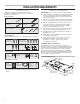

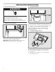

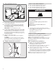

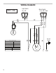
Table Of Contents

7
5. Mark hole locations
Lift the range hood into place and insert the mounting bracket
tabs through the slots in the back of the range hood.
Hold the range hood rmly in place with one hand and
bendeach mounting tab (A) upward approximately 90°.
Mark the hole at the power supply knockout (B).
OPTIONAL: Mark the hole in each mounting tab.
Remove the range hood and set it aside.
6. Drill electrical opening
Using a 1
1
/
4
" (3 cm) drill bit, drill the hole in the dot
markedpreviously at the electrical strain relief.
OPTIONAL: Using a 1/8" (3 mm) drill bit, drill pilot holes
for thedots marked previously at each mounting tab
atanapproximate 45° angle in an upward direction.
7. Prepare range hood vents
andmounting tabs
■ Install Strain Relief
Install a UL listed/CSA approved 1/2" (13 mm)
strainrelief(A).
■ Mounting Tabs
Start a #8-18 x 5/8" (4.2 x 16 mm) truss-head screw into
themounting tab (D) on each side of the range hood
asshown in the inset. Insert the screws approximately
2turns into the mounting tab holes.
■ Non-vent (Recirculating) Installations
Remove the (2) T10 Torx
®†
screws and remove the top,
front rectangular vent cover (B).
B
A
90˚
A
B
x2
C
†
®
TORX is a registered trademark of Acument Intellectual Properties, LLC.