30" (76.2 CM) AND 36" (91.4 CM) RANGE HOOD Installation Instructions and Use & Care Guide For questions about features, operation/performance, parts, accessories or service, call: 1-800-253-1301 or visit our website at www.whirlpool.com In Canada, call 1-800-807-6777 or visit our website at www.whirlpool.
State of California Proposition 65 Warnings: WARNING: This product contains one or more chemicals known to the State of California to cause cancer. WARNING: This product contains one or more chemicals known to the State of California to cause birth defects or other reproductive harm. IMPORTANT SAFETY INSTRUCTIONS WARNING: TO REDUCE THE RISK OF FIRE, ELECTRIC SHOCK, OR INJURY TO PERSONS, OBSERVE THE FOLLOWING: ■ Use this unit only in the manner intended by the manufacturer.
INSTALLATION REQUIREMENTS Tools and Parts Location Requirements Gather the required tools and parts before starting installation. Read and follow the instructions provided with any tools listed here. Tools needed Pencil Wire stripper #2 Phillips screwdriver Flat-blade screwdriver Drill with ¹⁄₈" (3 mm), ¹⁄₂" (13 mm), and 1¹⁄₄" (3 cm) bits Parts supplied IMPORTANT: Observe all governing codes and ordinances.
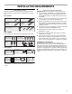
Product Dimensions Electrical Requirements 6⁹⁄₁₆" (16.7 cm) or 9⁹⁄₁₆" (24.4 cm) 2" (5.1 cm) 1" (2.5 cm) 4¹⁵⁄₁₆" (12.5 cm) ⁷⁄₈" (2.2 cm) 9" (22.9 cm) 29¹⁵⁄₁₆" (76.0 cm) or 35¹⁵⁄₁₆" (91.0 cm) 1¹⁄₂" (3.8 cm) 18⁵⁄₈" (47.3 cm) Installation Clearances Observe all governing codes and ordinances. Ensure that the electrical installation is adequate and in conformance with National Electrical Code, ANSI/NFPA 70 (latest edition), or CSA Standards C22.1-94, Canadian Electrical Code, Part 1 and C22.2 No.
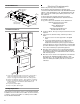
INSTALLATION INSTRUCTIONS 1. Disconnect power 3. Install Brackets WARNING Electrical Shock Hazard Disconnect power before servicing. Replace all parts and panels before operating. Failure to do so can result in death or electrical shock. 2. Mark Hole Locations ■ Using a #2 Phillips screwdriver, install the drywall anchors. ■ Using #8-18 x 1" (4.2 x 25 mm) flat-head #2 Phillips screws, install the mounting brackets using the upper holes.
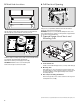
5. Mark Hole Locations 6. Drill Electrical Opening Lift the range hood into place and insert the mounting bracket tabs through the slots in the back of the range hood. Using a 1¹⁄₄" (3 cm) drill bit, drill the hole in the dot marked previously at the electrical strain relief. OPTIONAL: Using a ¹⁄₈" (3 mm) drill bit, drill pilot holes for the dots marked previously at each mounting tab at an approximate 45° angle in an upward direction. 7.
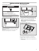
8. Mount Range Hood Option 1 - Direct Wire Installations ■ Use a UL Listed/CSA Approved wire connector and connect the 2 white wires (A) together. ■ Use a UL Listed/CSA Approved wire connector and connect the 2 black wires (B) together. WARNING Fire Hazard Electrically ground the blower. Use copper wire. ■ Lift the range hood into place, positioning the rear slots over the mounting brackets. Connect ground wire to green ground screw in terminal box.
RANGE HOOD USE The range hood is designed to remove smoke, cooking vapors and odors from the cooktop area. For best results, start the hood before cooking and allow it to operate several minutes after the cooking is complete to clear all smoke and odors from the kitchen. The hood controls are located on the front panel of the range hood. Range Hood Controls Off On Off High Low A B A A. Fan speed switch B.
3. Screw a 120V, 75W maximum, incandescent light bulb with E26 base into the socket. 4. Replace the lens cover by squeezing the cover and inserting the tabs into the slots. 5. Reconnect power. If the new light does not operate, make sure the light bulb is inserted correctly before calling service. Replacing the Incandescent Light Bulb Turn off the range hood and allow the light bulb to cool. 1. Disconnect power. 2. Squeeze the plastic lens cover and remove it from the hood.
ASSISTANCE OR SERVICE If you need service In Canada Please refer to the warranty page in this manual. If you need replacement parts If you need to order replacement parts, we recommend that you use only factory specified parts. Factory specified parts will fit right and work right because they are made with the same precision used to build every new appliance.
® WHIRLPOOL MAJOR APPLIANCE LIMITED WARRANTY ATTACH YOUR RECEIPT HERE. PROOF OF PURCHASE IS REQUIRED TO OBTAIN WARRANTY SERVICE. Please have the following information available when you call the Customer eXperience Center: ■ Name, address and telephone number ■ Model number and serial number ■ A clear, detailed description of the problem ■ Proof of purchase including dealer or retailer name and address IF YOU NEED SERVICE: 1.
SÉCURITÉ DE LA HOTTE DE CUISINIÈRE Votre sécurité et celle des autres est très importante. Nous donnons de nombreux messages de sécurité importants dans ce manuel et sur votre appareil ménager. Assurez-vous de toujours lire tous les messages de sécurité et de vous y conformer. Voici le symbole d’alerte de sécurité. Ce symbole d’alerte de sécurité vous signale les dangers potentiels de décès et de blessures graves à vous et à d’autres.
IMPORTANTES INSTRUCTIONS DE SÉCURITÉ AVERTISSEMENT : POUR RÉDUIRE LE RISQUE D'INCENDIE, CHOC ÉLECTRIQUE OU DOMMAGES CORPORELS, RESPECTER LES INSTRUCTIONS SUIVANTES : ■ Utiliser cet appareil uniquement dans les applications envisagées par le fabricant. Pour toute question, contacter le fabricant.
EXIGENCES D’INSTALLATION Outillage et pièces Exigences d’emplacement Rassembler les outils et pièces nécessaires avant d’entreprendre l’installation. Lire et observer les instructions fournies avec chacun des outils de la liste ci-dessous. IMPORTANT : Observer les dispositions de tous les codes et règlements en vigueur. ■ C'est à l'installateur qu'incombe la responsabilité de respecter les distances de séparation spécifiées sur la plaque signalétique.
Dimensions du produit Spécifications électriques 6⁹⁄₁₆" (16,7 cm) ou 9⁹⁄₁₆" (24,4 cm) 2" (5,1 cm) 1" (2,5 cm) 4¹⁵⁄₁₆" (12,5 cm) 1" (2,5 cm) 9" (22,9 cm) 29¹⁵⁄₁₆" (76,0 cm) ou 35¹⁵⁄₁₆" (91,0 cm) 1¹⁄₂" (3,8 cm) 18⁵⁄₈" (47,3 cm) Distances de dégagement à respecter Observer les dispositions de tous les codes et règlements en vigueur.
INSTRUCTIONS D’INSTALLATION 1. Déconnecter la source de courant électrique 3. Installation des brides AVERTISSEMENT Risque de choc électrique Déconnecter la source de courant électrique avant l'entretien. Replacer pièces et panneaux avant de faire la remise en marche. Le non-respect de ces instructions peut causer un décès ou un choc électrique. ■ À l’aide d’un tournevis Phillips n° 2, installer les chevilles d'ancrage.
5. Marquage de l'emplacement des trous 6. Perçage des ouvertures des câbles électriques Soulever la hotte et la mettre en place, et insérer les pattes des brides de montage dans les fentes situées à l'arrière de la hotte. Au moyen d'un foret de 1¹⁄₄" (3 cm), percer le trou à l'emplacement du serre-câble marqué précédemment. FACULTATIF : À l’aide d'un foret de ¹⁄₈" (3 mm), percer des avanttrous aux emplacements de chaque patte de montage marqués précédemment, à un angle d'environ 45° vers le haut. 7.
8. Montage de la hotte Option 1 - Installations avec raccordement par câblage direct ■ Connecter ensemble les 2 conducteurs blancs (A) à l'aide d'un connecteur de fils homologué UL/CSA. ■ Connecter ensemble les 2 conducteurs noirs (B) à l'aide d'un connecteur de fils homologué UL/CSA. WARNING Fire Hazard Electrically ground the blower. Use copper wire. ■ Soulever la hotte et la mettre en place en positionnant les encoches arrière sur les brides de montage.
UTILISATION DE LA HOTTE La hotte de cuisinière est conçue pour extraire fumée, vapeurs de cuisson et odeurs de la zone de la table de cuisson. Pour obtenir les meilleurs résultats, mettre le ventilateur de la hotte en marche avant d’entreprendre une cuisson, et laisser le ventilateur fonctionner pendant plusieurs minutes après l’achèvement d’une cuisson pour pouvoir évacuer de la cuisine toute trace d’odeur de cuisson, vapeur ou fumée. Les commandes de la hotte sont situées sur le panneau avant de la hotte.
3. Installer une ampoule à incandescence de 75 watts maximum, 120 V, à culot E12. 4. Réinstaller le cabochon : exercer une pression sur le cabochon pour pouvoir insérer les pattes dans les ouvertures d’insertion. 5. Reconnecter la source de courant électrique. Si la nouvelle lampe ne fonctionne pas, vérifier que l'ampoule est correctement insérée dans sa douille avant de demander l’intervention d’un dépanneur. Remplacement de l'ampoule à incandescence Éteindre la hotte et laisser l'ampoule refroidir. 1.
ASSISTANCE OU SERVICE Si vous avez besoin de service Pour plus d’assistance Consulter la page de garantie du présent manuel. Si vous avez besoin de plus d’assistance, vous pouvez soumettre par écrit toute question ou préoccupation à Whirlpool Canada à l’adresse suivante : Whirlpool Brand Home Appliances Centre pour l’eXpérience de la clientèle Whirlpool Canada 200 - 6750 Century Ave.
GARANTIE LIMITÉE DES GROS APPAREILS MÉNAGERS WHIRLPOOL® ATTACHEZ ICI VOTRE REÇU DE VENTE. UNE PREUVE D’ACHAT EST OBLIGATOIRE POUR OBTENIR L'APPLICATION DE LA GARANTIE.
Notes 23
® W10646402C /™ ©2014. Used under license in Canada. All rights reserved. Utilisé sous licence au Canada. Tous droits réservés.