30" (76.2 CM) AND 36" (91.4 CM) RANGE HOOD Installation Instructions and Use & Care Guide For questions about features, operation/performance, parts, accessories or service, call: 1-800-253-1301 or visit our website at www.whirlpool.com In Canada, call 1-800-807-6777 or visit our website at www.whirlpool.
State of California Proposition 65 Warnings: WARNING: This product contains one or more chemicals known to the State of California to cause cancer. WARNING: This product contains one or more chemicals known to the State of California to cause birth defects or other reproductive harm. IMPORTANT SAFETY INSTRUCTIONS WARNING: TO REDUCE THE RISK OF FIRE, ELECTRIC SHOCK, OR INJURY TO PERSONS, OBSERVE THE FOLLOWING: ■ Use this unit only in the manner intended by the manufacturer.
INSTALLATION REQUIREMENTS For 7" (17.8 cm) round vented installations Tools and Parts Gather the required tools and parts before starting installation. Read and follow the instructions provided with any tools listed here. Tools needed Metal snips Wire stripper #2 Phillips screwdriver Flat-blade screwdriver 7" (17.8 cm) round damper Part Number W10355451* Vent clamps as required 7" (17.8 cm) round vent mounting plate Part Number W10388168* For 3¹⁄₄" x 10" (8.3 x 25.
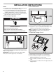
Product Dimensions Venting System 6⁹⁄₁₆" (16.7 cm) or 9⁹⁄₁₆" (24.4 cm) 2" (5.1 cm) Venting Methods 1" (2.5 cm) 4¹⁵⁄₁₆" (12.5 cm) 1" (2.5 cm) 9" (22.9 cm) 29¹⁵⁄₁₆" (76.0 cm) or 35¹⁵⁄₁₆" (91.0 cm) 1¹⁄₂" (3.8 cm) 18⁵⁄₈" (47.3 cm) NOTES: ■ Flexible vent is not recommended. Flexible vent creates both back pressure and air turbulence that greatly reduce performance. ■ The vent system is optional for this model. Vent system can terminate either through the roof or wall. Use 3¹⁄₄" x 10" (8.3 x 25.
For the most efficient and quiet operation: ■ Use no more than three 90° elbows. ■ Make sure there is a minimum of 24" (61 cm) of straight vent between the elbows if more than 1 elbow is used. ■ Do not install 2 elbows together. ■ Use clamps or duct tape to seal all joints in the vent system. ■ The vent system must have a damper. If roof or wall cap has a damper, do not use damper supplied with the range hood. ■ Use caulking to seal exterior wall or roof opening around the cap.
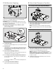
INSTALLATION INSTRUCTIONS NOTES: ■ Depending on your model, determine which venting method to use: roof, wall or non-vented (recirculating). ■ It is recommended that the vent system be installed before the range hood is installed. Go to “Venting System” in the “Installation Requirements” section if you need assistance. ■ Before making cutouts, make sure there is proper clearance within the ceiling or wall for the vent system. 3. Install Brackets 1.
5. Mark Hole Locations 6. Mark and Cut Vent Opening 3¹⁄₄" x 10" (8.3 x 25.4 cm) Rectangular Vent System Lift the range hood into place and insert the mounting bracket tabs through the slots in the back of the range hood. 45˚+ A A ■ Using a ¹⁄₂" (13 mm) drill bit, drill a hole in each of the dots marked previously on either the wall or upper cabinet. Using the outside edges of the holes, mark the vent opening. ■ Using a jigsaw or keyhole saw, cut the vent opening. 7" (17.
7. Drill Electrical Opening 9. Attach Vent Damper or Transition 3¹⁄₄" x 10" (8.3 x 25.4 cm) Rectangular Vent Damper Using a 1¹⁄₄" (3 cm) drill bit, drill the hole in the dot marked previously at the electrical strain relief. OPTIONAL: Using a ¹⁄₈" (3 mm) drill bit, drill pilot holes for the dots marked previously at each mounting tab at an approximate 45° angle in an upward direction. ■ 8. Prepare Range Hood Vents and Mounting Tabs x2 Using (2) short Phillips head screws, install the 3¹⁄₄" x 10" (8.
10. Mount Range Hood Option 1 - Direct Wire Installations ■ Use a UL Listed/CSA Approved wire connector and connect the 2 white wires (A) together. ■ Use a UL Listed/CSA Approved wire connector and connect the 2 black wires (B) together. WARNING Fire Hazard Electrically ground the blower. Use copper wire. ■ Lift the range hood into place, positioning the rear slots over the mounting brackets.
RANGE HOOD USE The range hood is designed to remove smoke, cooking vapors and odors from the cooktop area. For best results, start the hood before cooking and allow it to operate several minutes after the cooking is complete to clear all smoke and odors from the kitchen. The hood controls are located on the front panel of the range hood. A Range Hood Controls B A A. Fan speed switch B. On/Off light switch B C Operating the light Turn the light switch to the right 1 position for Low (night light).
Replacing the Incandescent Light Bulb Turn off the range hood and allow the light bulb to cool. 1. Disconnect power. 2. Squeeze the plastic lens cover and remove it from the hood. 3. Screw a 120V, 75W maximum, incandescent light bulb with E26 base into the socket. 4. Replace the lens cover by squeezing the cover and inserting the tabs into the slots. 5. Reconnect power. If the new light does not operate, make sure the light bulb is inserted correctly before calling service.
ASSISTANCE OR SERVICE When calling for assistance or service, please know the purchase date and the complete model and serial number of your appliance. This information will help us to better respond to your request. If you need replacement parts If you need to order replacement parts, we recommend that you use only factory specified parts. Factory specified parts will fit right and work right because they are made with the same precision used to build every new appliance.
7. Costs associated with the removal from your home of your major appliance for repairs. This major appliance is designed to be repaired in the home and only in-home service is covered by this warranty. 8. Repairs to parts or systems resulting from unauthorized modifications made to the appliance. 9. Expenses for travel and transportation for product service if your major appliance is located in a remote area where service by an authorized Whirlpool servicer is not available. 10.
SÉCURITÉ DE LA HOTTE DE CUISINIÈRE Votre sécurité et celle des autres est très importante. Nous donnons de nombreux messages de sécurité importants dans ce manuel et sur votre appareil ménager. Assurez-vous de toujours lire tous les messages de sécurité et de vous y conformer. Voici le symbole d’alerte de sécurité. Ce symbole d’alerte de sécurité vous signale les dangers potentiels de décès et de blessures graves à vous et à d’autres.
IMPORTANTES INSTRUCTIONS DE SÉCURITÉ AVERTISSEMENT : POUR RÉDUIRE LE RISQUE D'INCENDIE, CHOC ÉLECTRIQUE OU DOMMAGES CORPORELS, RESPECTER LES INSTRUCTIONS SUIVANTES : ■ Utiliser cet appareil uniquement dans les applications envisagées par le fabricant. Pour toute question, contacter le fabricant.
EXIGENCES D’INSTALLATION Pièces nécessaires Outillage et pièces Rassembler les outils et pièces nécessaires avant d’entreprendre l’installation. Lire et observer les instructions fournies avec chacun des outils de la liste ci-dessous.
Exigences d’emplacement IMPORTANT : Observer les dispositions de tous les codes et règlements en vigueur. ■ C'est à l'installateur qu'incombe la responsabilité de respecter les distances de séparation spécifiées sur la plaque signalétique. La plaque signalétique est située à l’intérieur de la hotte, sur la paroi de gauche. ■ Installer la hotte de cuisinière à distance de toute zone exposée à des courants d’air, comme fenêtres, portes et bouches de chauffage à fort débit.
Circuit d’évacuation Air d’appoint Méthodes d’évacuation REMARQUES : ■ L'emploi d’un conduit flexible est déconseillé. Un conduit flexible peut causer une rétro-pression et des turbulences de l’air, ce qui réduit considérablement la performance. Le circuit d'évacuation est facultatif pour ce modèle. ■ La sortie à l’extérieur du circuit d’évacuation peut se faire à travers le toit ou à travers un mur.
Calcul de la longueur du circuit d’évacuation Pour calculer la longueur effective du circuit d’évacuation nécessaire, additionner les longueurs équivalentes (en pieds ou mètres) de tous les composants utilisés dans le circuit. Circuit d’évacuation Composant Coude à 45° 2,5 pi (0,8 m) Coude à 90° 5,0 pi (1,5 m) Coude plat de 3¹⁄₄" x 10" (8,3 cm x 25,4 cm) 12 pi (3,7 m) Spécifications électriques Observer les dispositions de tous les codes et règlements en vigueur.
INSTRUCTIONS D’INSTALLATION REMARQUES : ■ Selon le modèle, déterminer la méthode d’évacuation à utiliser : évacuation à travers le mur ou le toit, ou recyclage. ■ Il est recommandé que l'installation du circuit d'évacuation soit réalisée avant celle de la hotte. Voir “Circuit d'évacuation” dans la section “Exigences d'installation” en cas de besoin. ■ Avant d’exécuter les découpages, vérifier qu'il existe un dégagement suffisant dans le plafond ou le mur pour le conduit d’évacuation. 3.
5. Marquage de l'emplacement des trous 6. Marquage et découpage de l'ouverture d'évacuation Système d’évacuation rectangulaire métallique de 3¹⁄₄" x 10" (8,3 x 25,4 cm) Soulever la hotte et la mettre en place, et insérer les pattes des brides de montage dans les fentes situées à l'arrière de la hotte. 45˚+ ■ À l'aide d'un foret de ¹⁄₂" (13 mm), percer un trou à chaque marque effectuée précédemment sur la paroi ou le placard supérieur.
7. Perçage des ouvertures des câbles électriques ■ Installations à circuit d’évacuation pour conduit rectangulaire de 3¹⁄₄" x 10" (8,3 x 25,4 cm) Pour les installations à évacuation par le dessus, retirer l’opercule amovible rectangulaire supérieur du conduit d'évacuation (C). OU Pour les installations à évacuation à travers le mur, retirer l’opercule amovible rectangulaire arrière du conduit d'évacuation (B).
REMARQUE : Un clapet anti-reflux circulaire de 7" (17,8 cm) (A), (pièce numéro W10355451), ainsi qu'une plaque de montage de conduit circulaire de 7" (17,8 cm) (B), (pièce numéro W10388168) sont disponibles en option. Pour des renseignements sur la commande, voir la section “Assistance ou service”. ■ 12. Raccordement électrique A En cas d'installation du clapet circulaire anti-reflux en option, le positionner par-dessus la plaque de montage de conduit circulaire. B 10.
13. Achever l'installation ■ Installer une ampoule à incandescence de 75 watts maximum, 120 V, à culot E26. Voir “Remplacement de l'ampoule à incandescence” dans la section “Entretien de la hotte”. ■ Réinstaller le filtre s'il a été retiré précédemment. Voir “Filtre à graisse métallique ou au charbon” dans la section “Entretien de la hotte”. ■ Contrôler le fonctionnement du ventilateur de la hotte et de la lampe. Voir la section “Utilisation de la hotte”.
ENTRETIEN DE LA HOTTE Nettoyage IMPORTANT : Nettoyer fréquemment la hotte et les filtres à graisse en suivant les instructions suivantes. Réinstaller le filtre à graisse avant de faire fonctionner la hotte. Surfaces externes : IMPORTANT : Ne pas utiliser de tampons de récurage savonneux, de nettoyants abrasifs, de crème à polir pour table de cuisson, de laine d’acier, de chiffons de lavage rugueux ou d’essuie-tout.
SCHÉMA DE CÂBLAGE Commutateur d'éclairage Arrêt - Faible - Élevé Contacteur du moteur Marche - Arrêt L 3 JA R 1 - 2 Arrêt 1 - 3 Faible 1 - L Élevé Diode redresseuse Commun Vitesse 1 R BL N Vitesse 2 N BL REMARQUE: Vitesse 1 non utilisée BL R Positions du commutateur d'éclairage 2 N R N 1 C25 Vis de mise à la terre Fréquence Intensité Puissance nominale 60 Hz 1,2 ±10% A 73 ±10% Watts BL 120 VCA N Caractéristiques du moteur Alimentation électrique Résistance du moteur Blanc - Rou
GARANTIE DE GROS APPAREIL MÉNAGER WHIRLPOOL CORPORATION GARANTIE LIMITÉE DE UN AN Pendant un an à compter de la date d’achat, lorsque ce gros appareil ménager est installé, utilisé et entretenu conformément aux instructions jointes à ou fournies avec le produit, Whirlpool Corporation ou Whirlpool Canada LP (ci-après désignées “Whirlpool”) décidera à sa seule discrétion de remplacer le produit ou de couvrir le coût des pièces spécifiées par l’usine et de la main-d’œuvre nécessaires pour corriger les vices de
Si vous résidez à l'extérieur des 50 États des États-Unis et du Canada, contactez votre marchand Whirlpool autorisé pour déterminer si une autre garantie s'applique. Pour assistance ou dépannage, voir d’abord la section “Dépannage” du Guide d'utilisation et d'entretien. Après avoir consulté la section “Dépannage”, on pourra trouver de l’aide supplémentaire à la section “Assistance ou service” ou en appelant Whirlpool. Aux 6/13 États-Unis, composer le 1-800-253-1301. Au Canada, composer le 1-800-807-6777.