
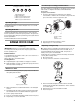
Installation Guide

12
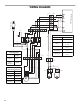
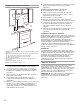
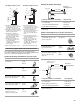
WIRING DIAGRAM
M
1
23
4
5
6
7
8
9
W
R
BK
GY
BR
Y
Power cord
BK
R
W
Y
BR
1
23
4
5
6
7
8
9
1
23
4
5
6
2
1
RED
W
BK
BU
Y/G
Y
CON 1
CON 2
CON 5
CO
N 8
CON 6
CO
N 7
R
BU
GY
CON 9
CON 10
Y/G
Y/G
Y/G
W
BK
W
BK
GY
GY
Push button board
Switch operation
Position
Connection
Off
No connection
Lamps
Low speed
Med speed
High speed
GY/Y
(L - LA)
GY/W
(L - 1)
GY/R
(L - 2)
GY/BK
(L - 3)
BU
Y
BU
Y
W
BK
BK
W
BU
Y
BU
BU
Capacitor
Varisitor
W
R
BK
GY
BU
Motor
characteristics
Power supply
Frequency
Power
absorption
120 VAC
60 Hz
240 W
Motor
resistance (Ohms)
BU-R
BU-GY
BU-BK
BU-W
Room
temperature
37.7
30.3
28.8 (max)
45.1 (min)
73.4˚F (23˚C)
CON3
CON 4