30" AND 36" (76.2 AND 91.4 CM) WALL-MOUNT CANOPY RANGE HOOD Installation Instructions and Use & Care Guide For questions about features, operation/performance, parts, accessories or service, call: 1-800-253-1301 or visit our website at www.whirlpool.com In Canada, call 1-800-807-6777 or visit our website at www.whirlpool.
TABLE OF CONTENTS TABLE DES MATIÈRES RANGE HOOD SAFETY .................................................................2 INSTALLATION REQUIREMENTS ................................................4 Tools and Parts ............................................................................4 Location Requirements................................................................4 Venting Requirements..................................................................5 Electrical Requirements ...................
IMPORTANT SAFETY INSTRUCTIONS WARNING: TO REDUCE THE RISK OF FIRE, ELECTRIC SHOCK, OR INJURY TO PERSONS, OBSERVE THE FOLLOWING: ■ Use this unit only in the manner intended by the manufacturer. If you have questions, contact the manufacturer. ■ Before servicing or cleaning the unit, switch power off at service panel and lock the service disconnecting means to prevent power from being switched on accidentally.
INSTALLATION REQUIREMENTS Tools and Parts Gather the required tools and parts before starting installation. Read and follow the instructions provided with any tools listed here. ■ 2 - 8 x 40 mm wall anchors ■ 4 - 10 x 50 mm wall anchors ■ T10 Torx®† adapter ■ T20®† Torx® adapter Tools needed ■ Level ■ Drill with 1¼" (3.2 cm), ¹⁄₈" (3.2 mm), and ⁵⁄₁₆" (7.
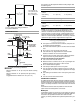
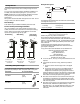
The chimneys can be adjusted for different ceiling heights. See the following chart. Vented Installations **27¹⁄₈" (68.9 cm) min. **41¹⁄₈" (104.5 cm) max. *27¹⁄₈" (68.9 cm) min. *45¹⁄₂" (115.6 cm) max. Min. ceiling height Max. ceiling height Electric cooking surface 7' 4" (2.23 m) 9' 5" (2.87 m) Gas cooking surface 7' 7" (2.31 m) 9' 5" (2.87 m) Non-vented (recirculating) Installations 17³⁄₁₆" (43.
Example vent system Venting Methods 90 elbow This canopy hood is factory set for venting through the roof or wall. A 6" (15.2 cm) round vent system is needed for installation (not included). The hood exhaust opening is 6" (15.2 cm) round. NOTE: Flexible vent is not recommended. Flexible vent creates back pressure and air turbulence that greatly reduce performance. Vent system can terminate either through the roof or wall. To vent through a wall, a 90° elbow is needed.
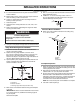
INSTALLATION INSTRUCTIONS Prepare Location ■ It is recommended that the vent system be installed before hood is installed. ■ Before making cutouts, make sure there is proper clearance within the ceiling or wall for exhaust vent. ■ Check your ceiling height and the hood height maximum before you select your hood. 1. Disconnect power. 2. Determine which venting method to use: roof, wall, or nonvented. 3. Select a flat surface for assembling the range hood. Place covering over that surface. 5.
Install Range Hood 1. Using 2 or more people, hang range hood on 2 mounting screws through the mounting slots on back of hood. For non-vented (recirculating) installation only: 1. Assemble the air deflector with the duct cover bracket using 4 - 4 x 8 mm screws. A C B B C A. Assembly screws B. Air deflector C. Duct cover bracket A 2. Measure from the bottom of the air deflector to the bottom of the hood outlet. A B A. Mounting screws B. Mounting slots C. Lower mounting screws D X C E 2.
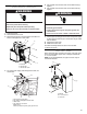
Make Electrical Connection WARNING 5. Use UL listed wire connectors and connect black wires (C) together. 6. Use UL listed wire connectors and connect white wires (E) together. WARNING Electrical Shock Hazard Disconnect power before servicing. Electrical Shock Hazard Replace all parts and panels before operating. Electrically ground blower. Failure to do so can result in death or electrical shock. Connect ground wire to green and yellow ground wire in terminal box. 1. Disconnect power. 2.
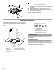
Secure the bottom of the duct with 2 - 4 x 8 mm screws. Complete Installation 1. For non-vented (recirculating) installations only, install charcoal filters over metal grease filter. See the “Range Hood Care” section. 2. Install metal filters. See the “Range Hood Care” section. 3. Check the operation of the range hood blower and light. See the “Range Hood Use” section. NOTE: To get the most efficient use from your new range hood, read the “Range Hood Use” section.
RANGE HOOD CARE Cleaning IMPORTANT: Clean the hood and grease filters frequently according to the following instructions. Replace grease filters before operating hood. 4. Bend spring clips back into place to secure the charcoal filter to the metal filter. Exterior Surfaces: To avoid damage to the exterior surface, do not use steel wool or soap-filled scouring pads. Always wipe dry to avoid water marks.
WIRING DIAGRAM R Gnd L Neu Push Button Switch W W BK Y/G BK BR BR Position Function Off No connection Brown - Yellow (L - LA) Lamps Y/G Low Speed Brown - White Med Speed Brown - Red BK R W BU Y Z BK La Switch Operation BK W R W BR Y/G Y Y High Speed (L - 1) (L - 2) Brown - Black Motor Resistance (Ohms) 5 6 7 R W Y BU 8 9 Y/G 4 BR 3 GY Y 2 BK 1 BU SE13F A Blue - Black 28.8 Blue - Gray 30.3 Blue - Red 37.7 Blue - White 45.1 Room Temp. M 73.
ASSISTANCE OR SERVICE When calling for assistance or service, please know the purchase date and the complete model and serial number of your appliance. This information will help us to better respond to your request. If you need replacement parts If you need to order replacement parts, we recommend that you use only factory specified parts. Factory specified parts will fit right and work right because they are made with the same precision used to build every new appliance.
WHIRLPOOL CORPORATION MAJOR APPLIANCE WARRANTY LIMITED WARRANTY For one year from the date of purchase, when this major appliance is operated and maintained according to instructions attached to or furnished with the product, Whirlpool Corporation or Whirlpool Canada LP (hereafter “Whirlpool”) will pay for Factory Specified Parts and repair labor to correct defects in materials or workmanship. Service must be provided by a Whirlpool designated service company.
SÉCURITÉ DE LA HOTTE DE CUISINIÈRE Votre sécurité et celle des autres est très importante. Nous donnons de nombreux messages de sécurité importants dans ce manuel et sur votre appareil ménager. Assurez-vous de toujours lire tous les messages de sécurité et de vous y conformer. Voici le symbole d’alerte de sécurité. Ce symbole d’alerte de sécurité vous signale les dangers potentiels de décès et de blessures graves à vous et à d’autres.
IMPORTANTES INSTRUCTIONS DE SÉCURITÉ AVERTISSEMENT : POUR RÉDUIRE LE RISQUE D'INCENDIE, CHOC ÉLECTRIQUE OU DOMMAGES CORPORELS, RESPECTER LES INSTRUCTIONS SUIVANTES : ■ Utiliser cet appareil uniquement dans les applications envisagées par le fabricant. Pour toute question, contacter le fabricant.
EXIGENCES D'INSTALLATION ■ 4 - pièces d'ancrage mural de 10 x 50 mm ■ Adaptateur T10 Torx®† Rassembler les outils et pièces nécessaires avant d’entreprendre l’installation. Lire et observer les instructions fournies avec chacun des outils de la liste ci-dessous. ■ Adaptateur T20®† Torx® Outils nécessaires IMPORTANT : Observer les dispositions de tous les codes et règlements en vigueur. Confier l'installation de la hotte à un technicien qualifié.
Installations sans décharge à l’extérieur (recyclage) Hauteur minimale Hauteur maximale sous plafond sous plafond **27¹⁄₈" (68,9 cm) min. **41¹⁄₈" (104,5 cm) max. *27¹⁄₈" (68,9 cm) min. *45¹⁄₂" (115,6 cm) max.
Exemple de circuit d'évacuation Méthodes d’évacuation Cette hotte a été configurée à l'usine pour la décharge de l'air aspiré à travers le toit ou à travers un mur. Un circuit d'évacuation en conduit rond de 6" (15,2 cm) (non fourni) est nécessaire pour l'installation. La hotte comporte une ouverture de sortie de diamètre 6" (15,2 cm). REMARQUE : On déconseille l'emploi de conduit flexible.
INSTRUCTIONS D’INSTALLATION Préparation de l’emplacement ■ Il est recommandé d’installer le circuit d’évacuation avant de procéder à l’installation de la hotte. ■ Avant d’exécuter les découpages, vérifier la disponibilité d’un dégagement suffisant dans le plafond ou le mur pour le conduit d’évacuation. ■ Avant de sélectionner la hotte à installer, mesurer la hauteur libre sous plafond et la hauteur maximum disponible sous la hotte. 1. Déconnecter la source de courant électrique. 2.
Installation de la hotte 1. À deux personnes au moins, suspendre la hotte aux 2 crochets de montage, à travers les encoches de montage à l’arrière de la hotte. Installations sans décharge à l'extérieur (recyclage) uniquement : 1. Fixer le déflecteur à la bride de cache-conduit à l’aide de 4 vis de 4 x 8 mm. A C B B C A. Vis d’assemblage B. Déflecteur d’air C. Bride de cache-conduit A 2. Mesurer la distance entre le bas du déflecteur et le bas de la sortie de la hotte. A B A. Vis de montage B.
Raccordement électrique AVERTISSEMENT 4. Acheminer le cordon d'alimentation du domicile à travers le serre-câble, dans le boîtier de connexion. A B C Risque de choc électrique Déconnecter la source de courant électrique avant l'entretien. D Replacer pièces et panneaux avant de faire la remise en marche. Le non-respect de ces instructions peut causer un décès ou un choc électrique. 1. Déconnecter la source de courant électrique. 2. Ôter le couvercle du boîtier de connexion. 3.
Installation des cache-conduits En cas d’utilisation des sections supérieure et inférieure du cache-conduit, pousser la section inférieure vers le bas, sur la hotte et soulever la section supérieure vers le plafond puis installer l'ensemble avec 2 vis de 4 x 8 mm. REMARQUE : Pour les installations avec décharge à l'extérieur, le cache-conduit supérieur peut être inversé pour dissimuler les fentes.
ENTRETIEN DE LA HOTTE Nettoyage IMPORTANT : Nettoyer fréquemment la hotte et les filtres à graisse en suivant les instructions suivantes. Réinstaller les filtres à graisse avant de faire fonctionner la hotte. 4. Replier les attaches à ressort pour les remettre en place afin de fixer le filtre à charbon au filtre métallique. Surfaces externes : Afin d'éviter d'endommager la surface externe, ne pas utiliser de tampons en laine d'acier ou de tampons à récurer savonneux.
R Terre L Neu BL BL N JA/VE MAR N MAR La Fonctionnement du commutateur N BL R BL MAR JA/VE JA JA Commutateur de bouton-poussoir SCHÉMA DE CÂBLAGE Position Connexion Pas de connexion Marron - Jaune Lampes (L - LA) Marron - Blanc Vitesse basse (L - 1) Vitesse moyenne Marron - Rouge (L - 2) Marron - Noir Vitesse élevée (L - 3) Off (arrêt) JA/VE R N BL BU JA Z N Résistance moteur (Ohms) BU 8 9 JA/VE 7 MAR 6 JA 5 BL 4 R 3 N JA 2 GRIS 1 BU SE13F A Bleu - Noir 28
ASSISTANCE OU SERVICE Lors d’un appel pour assistance ou service, veuillez connaître la date d’achat, le numéro de modèle et le numéro de série complets de l’appareil. Ces renseignements nous aideront à mieux répondre à votre demande. Si vous avez besoin de pièces de rechange Si vous avez besoin de commander des pièces de rechange, nous vous recommandons d’employer uniquement les pièces spécifiées par l’usine.
GARANTIE DES GROS APPAREILS MÉNAGERS WHIRLPOOL CORPORATION GARANTIE LIMITÉE Pendant un an à compter de la date d'achat, lorsque ce gros appareil ménager est utilisé et entretenu conformément aux instructions jointes à ou fournies avec le produit, Whirlpool Corporation ou Whirlpool Canada LP (ci-après désignées “Whirlpool”) paiera pour les pièces spécifiées par l'usine et la main-d'œuvre pour corriger les vices de matériaux ou de fabrication.
W10526059C © 2012 Whirlpool Corporation. All rights reserved. Used under license in Canada. Tous droits réservés. Utilisée sous licence au Canada.