
Installation Guide


3
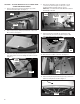
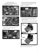
FIGURE 9
TAB
FRONT
PANEL
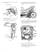
FIGURE 8
(3) SCREWS
12. Next remove the three (3) screws from the top of the front
panel as shown in Figure 8.
13. Remove front panel assembly from dryer by lifting panel
assembly up and off tabs (one each side) as shown in
Figure 9.
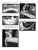
14. Next remove console mounting bracket by removing two (2)
screws securing bracket to cabinet left side panels, two (2)
screws from right side panel and one (1) screw from central
control bracket. Slightly lift assembly and remove from dryer.
See Figure 10A and 10B.
FIGURE 10A
(2) SCREWS -
LEFT SIDE
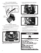
FIGURE 10B
(3) SCREWS
- RIGHT SIDE
CCU
BRACKET
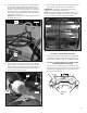
15. Remove the bulkhead assembly from dryer by rst
removing lint screen from dryer lint duct. See Figure 11.
FIGURE 11
LINT DUCT
LINT
SCREEN
BULKHEAD
ASSEMBLY
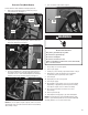
NOTE: Only on models with the CCU Bracket located on the left
side of the unit.