
Installation Guide


4
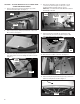
FIGURE 13
(3) SCREWS
LINT DUCT
CLIP
SCREW
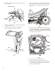
17. Remove lint duct by removing the four (4) screws and clip
as shown in Figure13.
NOTE: Slide lint duct down and away from dryer to remove.
18. Remove bulkhead assembly by rst removing four (4)
screws securing the bulkhead assembly to cabinet.
Slightly lift up on bulkhead assembly and at the same
time pulling away from drum working rollers off drum.
See Figure 14.
NOTE: During removal of bulkhead, take special notice of the
Lower Protective Shield to assure proper orientation during
reassembly.
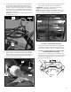
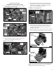
19. Swing bulkhead assembly to side and remove two (2)
harness clips to disconnect harness from bulkhead.
See Figure 15.
NOTE: Only on models with the CCU Bracket located on
the right side of the unit.
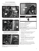
FIGURE 14
(4) SCREWS
LOWER
PROTECTIVE
SHIELD
FIGURE 15
BULKHEAD
(2) CLIPS - MAIN
HARNESS
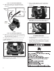
FIGURE 12
MOISTURE SENSOR
DISCONNECT BLOCK
MAIN HARNESS
DISCONNECT BLOCK
16. Disconnect moisture sensor disconnect block from main
harness disconnect block located at lower right side of
dryer. See Figure 12.
CCU
BRACKET