
Installation Instructions


6
Electrical Requirements
Observe all governing codes and ordinances.
Ensure that the electrical installation is adequate and in
conformance with National Electrical Code, ANSI/NFPA 70 (latest
edition), or CSA Standards C22.1-94, Canadian Electrical Code,
Part 1 and C22.2 No. 0-M91 (latest edition) and all local codes
and ordinances.
If codes permit and a separate ground wire is used, it is
recommended that a qualified electrician determine that the
ground path is adequate.
A copy of the above code standards can be obtained from:
National Fire Protection Association
1 Batterymarch Park
Quincy, MA 02169-7471
CSA International
8501 East Pleasant Valley Road
Cleveland, OH 44131-5575
■ A 120 volt, 60 Hz., AC only, 15-amp, fused electrical circuit is
required.
■ If the house has aluminum wiring, follow the procedure
below:
1. Connect a section of solid copper wire to the pigtail
leads.
2. Connect the aluminum wiring to the added section of
copper wire using special connectors and/or tools
designed and UL listed for joining copper to aluminum.
Follow the electrical connector manufacturer's recommended
procedure. Aluminum/copper connection must conform with
local codes and industry accepted wiring practices.
■ Wire sizes and connections must conform with the rating of
the appliance as specified on the model/serial rating plate.
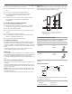
The model/serial plate is located behind the filter on the rear
wall of the range hood.
■ Wire sizes must conform to the requirements of the National
Electrical Code, ANSI/NFPA 70 (latest edition), or CSA
Standards C22. 1-94, Canadian Electrical Code, Part 1 and
C22.2 No. 0-M91 (latest edition) and all local codes and
ordinances.
INSTALLATION INSTRUCTIONS
Prepare Location
CAUTION: To reduce the risk of fire and electrical shock, install
the In-Line Smart Kit only with the range hood model series listed
in these instructions.
■ Before cutting or drilling into the ceiling or walls, make sure
there is proper clearance within the ceiling or wall for the vent
system.
■ When cutting or drilling into the ceiling or wall, do not
damage electrical wiring on other hidden utilities.
■ Determine which venting method to use: roof, or wall.
■ The In-Line Smart Kit must be installed to a secure structure
of the roof, ceiling, wall, or floor. The In-Line Smart Kit may
also be installed into a new or existing frame construction.
The structure must be capable of supporting 25 Ib (11.3 kg).
The installation holes on the in-line mounting bracket to be
used to mount the In-Line Smart Kit to the structure.
Prepare In-Line Smart Kit
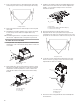
1. Using two or more people, move the In-Line Smart Kit and
the range hood to a workbench or work space.
2. Unpack all parts supplied with the In-line smart kit. Use the
“Tools and Parts” section of this manual to verify that all parts
have been included.
3. Remove the In-line-Smart assembly from the wooden
packaging material
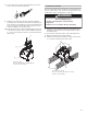
NOTE: Do not move the In-Line Smart Kit to the mounting
location until the range hood blower motor has been installed in
the in-line housing. Do not install the range hood until the In-Line
Smart Kit and vent system have been installed.
IMPORTANT: Installation of the In-Line Smart Kit is model
specific. Before installing, determine the model number of the
range hood to be used with the In-Line Smart Kit. See the
appropriate “Install In-Line Smart Kit” section.
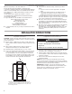
A. Distance between installation holes: 24" (61 cm),
19½" (49.2 cm), 18" (46.2 cm), and 14½" (36.8 cm)
B. Distance between installation holes: 7¾" (19.7 cm)
C. Mounting structure
C
A
B
WARNING
Excessive Weight Hazard
Use two or more people to move and install
range hood.
Failure to do so can result in back or other injury.