
Instruction manual


10
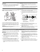
Make Electrical Connections—Models with Factory-Installed Electric Heat
1. Determine the number of circuits needed to supply the heater
with electrical power (1, 2, or 3 circuits). See the air handler
Accessory Kit label for number of circuits and ratings.
2. Disconnect all power supplies.
3. Knock out the correct number of knockouts (1, 2, or 3), and
install UL listed wires and fittings.
4. Connect appropriate size wire to the circuit breaker terminals.
If circuit breakers are not provided, a terminal block is
provided.
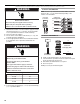
5. Connect green ground wire(s) (1, 2, or 3) to ground terminal(s)
(1, 2, or 3) marked “GND.”
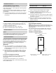
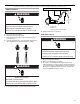
Connect to Circuit Breaker
NOTE: There are 2 ground terminals marked “GND” shown here.
There may be 1, 2 or 3 ground terminals depending on the
number of circuit breakers.
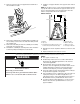
Connect to Terminal Block
6. Install conduit opening plugs in any unused openings.
7. If circuit breakers or pull disconnects are used, the front panel
knockouts will need to be removed.
8. Reinstall the air handler blower access panel.
9. Reconnect power.
10. Dispose of/recycle all remaining parts.
WARNING
Electrical Shock Hazard
Disconnect all power supplies before servicing.
Replace all parts and panels before operating.
Failure to do so can result in death or electrical shock.
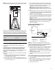
WARNING
Electrical Shock Hazard
Electrically ground electric heater.
Connect ground wire to ground terminal
marked “GND.”
Use copper wire rated for supply connection.
Correct wire gauge is shown in the chart below.
Failure to follow these instructions can result in
death or electrical shock.
Rating Plate Ampacity
21 - 30
31 - 40
41 - 60
AWG
10
8
6
GND
Field Supply
Ground Wires
Circuit 1
Circuit 2
L1
L2
L1
L2
208/230 Volt
Field Supply Wires
ON
OFF
60
ON
OFF
60
GND
L1
L2
L1
L2
208/230 Volt
Field Supply Wires
Field Supply
Ground Wires