
Instruction manual


5
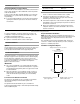
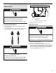
3. Remove screws from the coil support bracket and lift off of
the air handler. Set aside.
4. Remove the coil/drain pan assembly by lifting and sliding out.
The assembly consists of the coil, the bottom drain pan and
the side drain pan.
5. Remove the side drain pan from the coil/drain pan assembly
and install on the opposite side.
6. Reinstall the coil/drain pan assembly in the same orientation
as before by lifting and sliding into the air handler.
7. Install the coil support bracket on the opposite side of the air
handler.
NOTE: For models 2.5 tons to 5 tons, the bracket attached to the
top cap will need to be switched to the opposite side of the coil.
This is to prevent blowoff in the horizontal position when the
airflow is changed from left-hand to right-hand.
After Conversion
8. Determine knockouts required for drain line connections and
remove.
9. Replace the blower and coil access covers.
Electrical Requirements—Models Without Factory-Installed Electric Heat
NOTES:
■ Use copper conductors only.
■ All field wiring must be done in accordance with National
Electrical Code, applicable requirements of UL and local
codes where applicable.
■ Electrical wiring, disconnect means and overcurrent
protection are to be supplied by the installer. Refer to the air
handler rating plate for maximum overcurrent protection,
minimum circuit ampacity, as well as operating voltage.
■ The power supply must be sized and protected according to
the specifications supplied on the product.
■ This air handler is factory-configured for 120-volt or 240-volt,
single phase, 60 cycles. For 208-volt applications, see
“208-Volt Conversion” in the “Make Electrical Connections—
Models Without Factory-Installed Electric Heat” section.
■ For optional electric heater applications, see “Accessories.”
Refer to the instructions provided with the accessory for
proper installation.
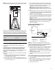
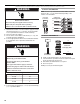
A. Coil support bracket screws
A
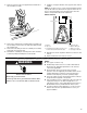
A. Blower
B. Top cap
C. Coil/drain pan assembly (consists of coil,
bottom drain pan and side drain pan)
D. Side drain pan
E. Bottom drain pan
F. Filter access door
G. Coil support bracket
G
F
E
D
B
A
C
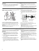
WARNING
Electrical Shock Hazard
Electrically ground air handler.
Connect ground wire to ground terminal marked “GND”.
Failure to do so can result in death or electrical shock.