
Instruction manual


7
NOTE: If any damages are discovered and reported to the carrier,
do not install the air handler because your claim may be denied.
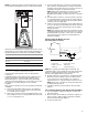
If a filter is to be installed at the air handler, remove the 2 screws
from the filter access panel and slide in the appropriate filter. See
the Filter Size Chart to ensure that the correct filter is installed.
Install Condensate Drain
The air handler is provided with ³⁄₄" NPT condensate drain
connections.
A field-fabricated secondary drain pan, with a drainpipe to the
outside of the building, is required in all installations over a
finished living space or in any area that may be damaged by
overflow from the main drain pan. In some localities, local codes
may require an secondary drain pan for any horizontal
installation.
Make sure the air handler is level so that the drain pan will empty
completely.
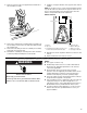
1. Remove the appropriate drain knockouts. See “Drain Pan
Connections” section. You may need to remove the indoor
coil assembly from the cabinet.
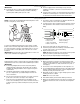
2. Remove any web from inside any threaded drain pan hole to
which a drain line is to be connected. Gently remove the web
so as not to damage the coil.
3. Connect primary drain line connection to the primary drain
pan connection. The primary drain connection is flush with
the bottom of the inside of the pan. Secondary connection is
raised above the bottom of the inside of the pan.
NOTE: When making drain fitting connections to the drain
pan, hand tighten. Using a sealant is recommended.
Overtightening the fittings can split connections on the drain
pan.
4. Secondary drain connections, if used, should be connected
to a separate drainage system. Run the secondary drain line
to a place where the occupant would notice if water started
coming from the secondary drain.
5. Install a 3" trap in both the primary and secondary drain lines
as close to the unit as practical. Make sure the top of the trap
is below the connection to the drain pan to allow complete
drainage of the pan.
NOTE: Horizontal runs must also have an anti-siphon air vent
(standpipe) installed ahead of the horizontal run. See “Typical
Condensate Drain Connection” in this section. An extremely
long horizontal run may require an oversized drain line to
eliminate air trapping.
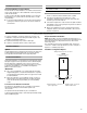
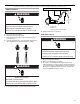
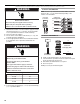
Typical Condensate Drain Connection
(secondary drain not shown)
NOTE: Do not operate air handler without a drain trap. The
condensate drain is on the negative pressure side of the blower;
therefore, air being pulled through the condensate line will
prevent positive drainage without a proper trap.
6. Route the drain line to the outside or to an appropriate drain.
Drain lines must be installed so they do not block service
access to the front of the air handler. A 24" clearance is
required for filter, coil, or blower removal and service access.
NOTE: Check local codes before connecting the drain line to
an existing drainage system.
7. Insulate the drain lines where sweating could cause water
damage.
Test condensate drain pan and drain line after installation:
1. Pour several quarts of water into drain pan, enough to fill
drain trap and line.
2. Check to make sure the drain pan is draining completely, no
leaks are found in drain line fittings, and water is draining
from the end of the primary drain line.
3. Correct any leaks found.
Filter Size Chart
Model Filter Size
18 / 24 16" x 20"
30 / 36 18" x 20"
42 / 48 / 60 18" x 25"
A. Air handler
B. Drain connection
C. Drain line
D. Anti-siphon air vent
E. Drain trap
F. Auxiliary drain pan
3.00" Min.
1.00" Min.
12.00"Max.
A
B
D
E
C
F