
Instruction manual


8
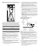
Install Ductwork
IMPORTANT:
■ Install ductwork in accordance with NFPA 90B Standard for
the Installation of Warm Air Heating and Air-Conditioning
Systems (latest edition) and any local codes.
■ Connect supply air duct to the flange on top of the air
handler. If an isolation connector is used, it must be non-
flammable.
■ A return air duct system is recommended. If the air handler is
installed in a confined space or closet, the entire duct cross
sectional area must meet minimum return air free area.
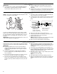
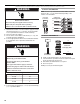
Verify Orifice Size
NOTE: Some models are equipped with thermal expansion valve
and do not require any orifice change.
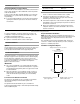
For factory installed thermal expansion valves, attach sending
bulb to suction line with strap. Bulb should be positioned 1 ft or
less from the header connection and situated at the 4 o’clock or
8 o’clock position. Secure tightly and cover with cork or foam
insulation.
IMPORTANT: The proper orifice size is dependent on indoor coil/
outdoor unit combination and application.
1. Consult the outdoor unit literature to determine whether the
indoor unit has the correct orifice installed.
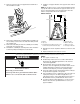
2. If a change of the orifice is required, loosen the brass hex nut
and separate the orifice extension stub from the brass hex
fitting.
3. Remove the orifice with an orifice extractor tool.
4. Insert the proper orifice into the fitting, seal end first. Make
sure the orifice is free to move in the fitting.
5. Replace the brass hex nut.
NOTE: Overtightening the brass hex nut will crush the gasket
and may result in a system leak or stuck piston.
6. Dispose of/recycle all packaging and unused parts.
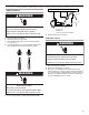
Connect Refrigerant Lines
Refrigerant lines must be connected by a licensed, EPA certified
refrigerant technician in accordance with established procedures.
IMPORTANT:
■ Connecting refrigerant lines must be clean, dehydrated,
refrigerant-grade copper lines. Air handler coils should be
installed only with specified line sizes for approved system
combinations.
■ Handle the refrigerant lines gently during the installation
process. Sharp bends or possible kinking in the lines will
cause a restriction.
■ Do not remove the caps from the lines or system connection
points until connections are ready to be completed.
1. Route the suction and liquid lines from the fittings on the
indoor coil to the fittings on the outdoor unit. Run the lines in
as direct a path as possible avoiding unnecessary turns and
bends.
2. Make sure that the suction line is insulated over the entire
exposed length and that both suction and liquid lines are not
in direct contact with floors, walls, ductwork, floor joists, or
other piping.
3. Connect the suction and liquid lines to the evaporator coil.
4. To avoid damaging the rubber grommets in the cabinet while
brazing, slide the rubber grommets over the refrigerant lines
until they are away from the heat source.
5. Braze with an alloy of silver or copper and phosphorus with a
melting point above 1,100°F.
NOTE: Do not use soft solder.
6. Reinstall the rubber grommets after brazing is finished.
7. Make sure air handler has been put in place according to the
Installation Instructions and is connected to the refrigerant
lines.
A. Thermal expansion valve
A
A. Distributor fitting
B. Piston orifice
C. Ring seal (supplied)
D. Orifice extension stub
E. 0.812" brass hex nut
F. Brass hex fitting
G. Mounting flange
A
G
C
D
B
E
F