
LP Gas Conversion Instructions


7
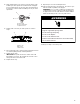
4. Apply masking tape to the end of a 7 mm nut driver to help
hold the gas orifice spud in the nut driver while changing it.
Press nut driver down onto the gas orifice spud and remove
by turning it counterclockwise and lifting out. Set gas orifice
spud aside. See Step 4 of the “Convert from Natural Gas to
LP Gas” section.
5. Replace with correct Natural gas orifice spud. See the charts
in Step 1.
6. Place LP gas orifice spuds in plastic parts bag for future use
and keep with the package containing literature.
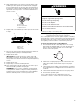
7. Replace burner base.
IMPORTANT: The igniter electrode is ceramic and could
break during conversion. Be sure that the electrode comes
through the hole in the burner head smoothly while tightening
screws.
8. Replace burner cap.
9. Repeat steps 1-8 for the remaining burners.
10. Open shutoff valve in the gas supply line. The valve is open
when the handle is parallel to the gas pipe.
REMEMBER: Once you have completed converting all the
cooktop burners, test the cooktop for leaks by brushing on
an approved noncorrosive leak-detection solution. Bubbles
will show, indicating a leak. Correct any leaks found.
11. Plug in cooktop or reconnect power.
Lighting the Electronic Igniters
The cooktop burners use electronic igniters in place of standing
pilots. When the cooktop control knob is pushed in and turned to
the LITE position, the system creates a spark to light the burner.
This sparking continues until the control knob is pushed in.
To Check Operation of the Cooktop Burners:
1. Push in and turn knobs to the LITE position. The cooktop
burner flame should light within 4 seconds. The first time a
burner is lit, it may take longer than 10 seconds to light
because of air in the gas line.
2. If burners do not light properly, turn the control knob to the
OFF position. Make sure the burner cap is in the proper
position.
3. Check that the power supply cord is plugged in. Check that
the circuit breaker has not tripped or the household fuse has
not blown.
4. Check that the manual shutoff valve is in the open position.
5. Check burner operation again.
If one or all of the burners do not light at this point, see
“Assistance or Service” section in the Use and Care Guide.
A. Orifice spud
B. Orifice spud holder
C. Spark electrode
A. Burner cap
B. Electrode
C. Burner base
B
A
C
A
B
C
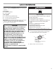
Electrical Shock Hazard
Plug into a grounded 3 prong outlet.
Do not remove ground prong.
Do not use an adapter.
Do not use an extension cord.
Failure to follow these instructions can result in death,
fire, or electrical shock.
WARNING