
Instruction Sheet


4
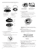
The gas pressure regulator has 2 settings that are stamped on
either side of the cap. Turn the cap and reinstall into regulator
with the stamp “LP” visible from the outside of the regulator.
Style 2: The access cap has a slot in it or a hex shape, without
any printed text.
Remove the access cap by using a flat - blade screwdriver or
wrench turning the access cap counter clockwise.
If Seven Universe is printed on the regulator, unthread the spring
retainer by rotating it counter clockwise. If Maxitrol is printed
on the regulator then apply force to the flat side of the spring
retainer to remove it.
Turn over the spring retainer to place the disk on the spring
retainer far from the access cap.
Install the Seven Universe spring retainer by turning it clockwise
to thread it fully into the access cap, or for the Maxitrol spring
retainer by applying pressure to snap the spring retainer into the
access cap.
Reinstall the cap and seal onto the regulator by turning
clockwise.
4. Test the gas pressure regulator and gas supply line.
The regulator must be checked at a minimum 1” (2.5 cm)
water column above the set pressure. The inlet pressure to
the regulator should be as follows for operation and checking
the regulator setting:
Propane Gas:
Minimum pressure 10” (25.4 cm) W.C.P.
Supply pressure 14” (35.5 cm) W.C.P.
Gas Supply Pressure Testing
Line pressure testing above 1/2 psi (3.5 kPa) gauge
(14” [35.5 cm] WCP)
The cooktop and its individual shutoff valve must be
disconnected from the gas supply piping system during any
pressure testing of that system at test pressures in excess of
½ psi (3.5 kPa).
Line pressure testing at 1/2 psi (3.5 kPa) gauge
(14” [35.5 cm] WCP) or lower
The cooktop must be isolated from the gas supply piping
system by closing its individual manual shutoff valve during
any pressure testing of the gas supply piping system at test
pressures equal to or less than ½ psi (3.5 kPa).
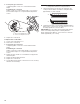
5. If the burner grates are installed, remove them.
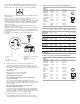
Use the following charts to match the correct gas orifice
spud with the burner location and model being converted.
A. Access cap
B. Seal
C. Regulator
D. Disk on Spring Retainer
E. Spring Retainer in Natural Gas
Position
F. Spring Retainer in LP Gas
Position
A
B
C
F
D
E
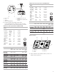
Propane Gas Orifice Spud Chart for Kit W10676661
Burner Models for Kit W11173306
Propane Gas Orifice Spud Chart for Kit W10676662
Burner
Rating
ColorStamp (A)Size
5,000 BTU Green660.66 mm
7,000 BTU White750.75 mm
8,000 BTU Orange79 0.79 mm
11,000 BTURed 97 0.97 mm
13,000 BTUYellow 108 1.08 mm
16,000 BTUPink 115 1.15 mm
12,000 BTU
Inner
Outer
Brown
Brown
85
48
0.85 mm
0.48 mm
11,000 BTU
Inner
Outer
Black
Black
89
40
0.89 mm
0.40 mm
A. Size stamp
Model No.Left
Front
Left
Rear
Center
Inner
Center
Outer
Right
Rear
Right
Front
WCG55US0H
MGC7430D
ICS500DS00
66
Green
108
Ye llow
N/AN/A 97
Red
75
White
WCG77US0H
MGC9530D
75
Green
79
Pink
108 N/A66
Re
d
75
White
KCGS350E
ICS655DS00
75
White
79
Orange
85
Brown
48
Brown
66
Green
75
White
WCG55US6H
MGC7536D
75
White
75
White
97
Red
N/A66
Green
97
Red
MGC9536D
W
CG97US0H
KCGS356E
75
White
75
White
85
Brown
48
Brown
66
Green
97
Red
75
White
79
Orange
89
Black
40
Black
66
Green
75
White
WCG97US6H
75
White
75
White
89
BlackBlack
40 66
Green
97
Red
Burner
Rating
ColorStamp (A)Size
5,000 BTU
White
66 0.66 mm
A. Size stamp
6,000 BTUGreen 70 0.70 mm
9,100 BTUBlac
k890.89 mm
11,000 BTU Orange 97
0.97 mm
13,000 BTU
Inner
Outer
Blue
Brown
45
97
0.45 mm
0.97 mm
14,000 BTU
Inner
Outer
Blue
Ye llow
45
101
0.45 mm
1.01 mm
16,000 BTU
Inner
Outer
Blue
Red
45
105
0.45 mm
1.05 mm
9,000 BTU
Inner
Outer
Pink
Pink
40
80
0.40 mm
0.80 mm
A
A
66 115N/A N/A9
77
5
WhiteOrange YellowGreen
White