
Installation Instructions

5
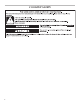
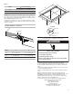
Table 1
Model CUT OUT (range)
F J
24" 20
3
/
8
" (51.7 cm) 21
7
/
8
" (55.6 cm)
30" 20
3
/
8
" (51.7 cm) 29
9
/
16
" (75.1 cm)
36" 20
3
/
8
" (51.7 cm) 35
9
/
16
" (90.3 cm)
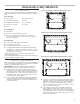
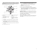
NOTE: After you make the countertop cutout, some installations
may require notching down the base cabinet side walls to clear
the cooktop base. To avoid this modication, use a base cabinet
with sidewalls wider than the cutout.
If cabinet has a drawer, a 5
1
∕
8
" (13 cm) depth clearance from the
countertop to the top of the drawer (or other obstruction) in base
cabinet is required.
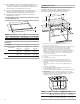
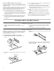
Flush Installation - Frameless
Model X Y
24" 25
13
/
16
"
(65.5 cm) 21
7
/
16
" (54.5 cm)
30" 31"
(78.7 cm) 21
7
/
16
" (54.5 cm)
36" 36
1
/
2
"
(92.7 cm) 21
7
/
16
" (54.5 cm)
Electrical Requirements
If codes permit and a separate ground wire is used, it is
recommended that a qualied electrical installer determine that
the ground path and wire gauge are in accordance with local
codes.
Check with a qualied electrical installer if you are not sure the
cooktop is properly grounded.
It is not recommended to have a fuse in the neutral or ground
circuit.
Make sure that the electrical connection and wire size are
adequate and in conformance with the National Electrical Code,
ANSI/NFPA 70-latest edition or CSA Standards C22.1-94,
Canadian Electrical Code, Part 1 and C22.2 No.O-M91-latest
edition, and all local codes and ordinances.
A copy of the above code standards can be obtained from:
National Fire Protection Association
1 Batterymarch Park
Quincy, MA 02169-7471
CSA International
8501 East Pleasant Valley Road
Cleveland, OH 44131-5575
1/4" (6 mm)
1³⁄₁₆" (3 cm)
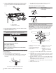
WARNING
Electrical Shock Hazard
Disconnect power before servicing.
Use 8 gauge copper wire.
Electrically ground cooktop.
Failure to follow these instructions can result in death,
fire, or electrical shock.
X
Y
A
Detail A
R8 ± 0.5
R5.5 ± 0.5
Glass radius 6 mm