Installation Instructions Undercounter Dishwasher Instructions d'installation Lave-vaisselle encastré Table of Contents.............................................................................2 Table des matières.........................................................................
Table of Contents Installation Instructions. . . . . . . . . . . . . . . . . . . . . . . . . . . . . 6 Dishwasher Safety . . . . . . . . . . . . . . . . . . . . . . . . . . . . . . . . . 2 Installation Requirements . . . . . . . . . . . . . . . . . . . . . . . . . . . 3 Prepare cabinet opening using existing utility hookups . . . . . . . . . . . . . . . . . . . . . 6 Tools and parts . . . . . . . . . . . . . . . . . . . . . . . . . . . . . . . . .
Installation Requirements Tools and Parts Location Requirements Gather the required tools and parts before starting installation. Do not run drain lines, water lines or electrical wiring where they can interfere with or contact dishwasher motors or legs. All installations Tools needed: • Phillips screwdriver Parts needed: • Flat - blade screwdriver • measuring tape or ruler • 90° elbow with 3/8" N.P.T. external threads on one end. (The other end must fit your water supply line.
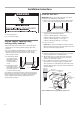
Product dimensions Cutout dimensions 22" (59cm)* 34" to 35" (86.4 cm to 88.9 cm)* All surfaces must be free from intrusions 32-1/2" (82.5 cm) min. 35" (88.9 cm) max 24" (61 cm) min. 4" (10.2 cm) 18" (45.7 cm) 6" (15.2 cm) * to front of door frame SIDE VIEW 17-5/8" (44.8 cm) min. 18" (45.7 cm) max. 17-1/2" (44.5 cm) min. 18" (45.7 cm) max. *Underside of countertop to floor. Cut holes in shaded area of cabinet walls or floor for plumbing and electrical service. Note: ADA installation, 32-1/2" (82.
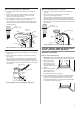
Drain Requirements Electrical Requirements • Use the new drain hose supplied with your dishwasher. If this is not long enough, use a new drain hose with a maximum length of 10 feet (3.05 m) that meets all current AHAM/IAPMO test standards, is resistant to heat and detergent, use 5/8”(1.58cm) or 7/8”(2.2cm) inside diameter hose and a coupler to connect the two hose ends. Secure the connection with two clamps Contact a qualified electrician.
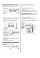
Installation Instructions WARNING Install the drain hose IMPORTANT: Always use a new drain hose even when installing a new replacement dishwasher. 1. Drill a 1-1/2" (3.8 cm) diameter hole in cabinet wall or floor on the side of the opening closest to the sink. 2. Connect drain hose to waste tee or waste disposer using one of the following methods: 1. Disconnect power. • Option 1, Waste disposer – with air gap 2. Turn off water supply.
Option 2, No waste disposer – with air gap: Option 4, No waste disposer – no air gap: 1. Cut end of drain hose if needed (do not cut ribbed section). 1. Cut end of drain hose if needed (do not cut ribbed section). 2. Attach drain hose to air gap with large spring-type clamp. If the drain hose was cut, use a 1-1/2" to 2" (3.8 to 5 cm) screw-type clamp*. 2. Attach drain hose to waste tee with 1-1/2" to 2" (3.8 to 5 cm) screw-type clamp*. 3.
Option 2, Power supply cord method: NOTE: A mating, three prong, ground-type wall receptacle is required in a cabinet next to the dishwasher opening. 2. Connect drain hose to waste tee or waste disposer using one of the following methods: • Option 1, Waste disposer – with air gap • Option 2, No waste disposer – with air gap 1. Drill a 1-1/2" (3.8 cm) hole in the cabinet rear or side. Preferred and optional locations are shown.
Option 2, No waste disposer – with air gap: Option 4, No waste disposer – no air gap: 1. Cut end of drain hose if needed (do not cut ribbed section). 1. Cut end of drain hose if needed (do not cut ribbed section). 2. Attach drain hose to air gap with large spring-type clamp. If the drain hose was cut, use a 1-1/2" to 2" (3.8 to 5 cm) screw-type clamp*. 2. Attach drain hose to waste tee with 1-1/2" to 2" (3.8 to 5 cm) screw-type clamp*. 3.
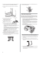
2. Remove four screws attaching toekick panel and lower panel to dishwasher using a Phillips screwdriver. 8. Extend leveling legs out from the dishwasher base, 1/4" less than opening height. 3. Remove panels and set panels aside on a protective surface. leveling leg Check door spring tension 4 toekick screws With another person holding the dishwasher to prevent it from tipping, open and close the door a few times.
5. Check that water line is on the left side of opening and insert the drain hose through the hole in cabinet. Make Electrical Connection 6. Slowly move dishwasher completely into cabinet opening so that the front corners of the dishwasher door are flush with the cabinet doors. Do not kink or pinch copper tubing, drain hose, power supply cord or direct wire between dishwasher and cabinet. Check “Electrical requirements” section.
ground Connect to water supply white Helpful Tip: black Compression fittings: a. Slide nut onto copper tubing about 1" (2.5 cm). b. Slide ferrule onto the tubing. Do not position ferrule on the end of the tubing. c. Put the tubing into the elbow as far as it will go. 4. Tighten clamp connector or conduit connector screws. 5. Reinstall terminal box cover with wires inside terminal box. d. Slide the nut and ferrule forward and start the nut onto the elbow threads.
Remove towel from dishwasher. 4. The drain hose molded end will fit 5/8" (16mm), 3/4" (19mm) or 1" (25.4mm) diameter connections on the air gap, waste tee or disposer. Cut on the marked line as required for your installation. IMPORTANT: Do not cut corrugated portion of hose. cutting lines 3/4" 1" 3. Check that the dishwasher is level and centered side to side in the opening. 4. Check that the tub flange aligns with the front face of the cabinet frame. 5.
Power supply cord method: Complete installation WARNING 1. Place the lower panel behind the toekick panel. 2. Place 2-piece toekick against the legs of the dishwasher. 3. Place the inner toekick piece (with slots) against the toekick bracket. The slots should align with toekick bracket screw holes. Allow the bottom edge of the lower toekick to touch the floor. 4. Place larger toekick over the inner piece and install 4 toekick screws. Use additional 2 screws for installations over 33-1/2" (85.09 cm) high.
Table des matières Instructions d'installation. . . . . . . . . . . . . . . . . . . . . . . . . . . . . 6 Préparer l'ouverture de l'armoire à l'aide des raccords de service existants . . . . . . . . . . . . . . . 6 Préparer l'ouverture de l'armoire lorsqu'il n'existe pas de raccord de service. . . . . . . . . .. .. .. 7 Préparer le lave-vaisselle . . . . . . . . . . . . . . . . . . . . . . . . . . . . 9 Effectuer le raccordement électrique. . . . . . . . . . . . . . . . . . .
Configuration requise pour l'installation Outils et pièces Configuration requise pour l'emplacement Rassemblez le s pièces et outils requis avant d e commencer l'in stallation. N'installez pas les conduites de vida nge, les conduites d'eau ou le câblage électrique à un endroit où ils pe uvent interférer avec ou toucher les moteurs ou les pieds du lave-vaisselle. L'emplacement d'installation du lave-vaisselle doit disposer d'un dégageme nt entre les moteurs et le plancher.
Dimensions du produit Dimensions de découpe 22 po (59 cm)* Toutes les surfaces doivent être dépourvues d'intrusions 32-1/2 po (82,5 cm) min., 35 po (88,9 cm) max. 34 po à 35 po (86,4 cm à 88,9 cm)* 24 po (61 cm) min. 4 po (10,2 cm) 18 po (45,7 cm) 6 po (15,2 cm) à l'ava nt du cadre de porte VUE LATÉRALE 17-5/8 po (4 4,8 cm) min. 18 po (45,7 cm) max. 17-1/2 po (44,5 cm) min. 18 po (45,7 cm) max. *Dessous du comptoir au plancher.
Configuration requise pour la vidange Utilisez le nouveau tuyau de vidange fourni avec votre lavevaisselle. S'il n'e st pas assez long, utilisez un nouveau tuyau de vidange d'une longueur maximale de 10 pi (3,05 m) conforme à toutes les normes actuelles de test AHAM/IAPMO, résistant à la chaleur et aux détergents; utilisez u n tuyau de diamètre interne 5/8 po (1,5 8 cm) ou 7/8 po (2,2 cm)et un coupleur pour racco rder les deux extrémités du tuyau.
Instructions d'installation AVERTISSEMENT Installer le tuyau de vidange IMPORTANT : Utilisez toujours un nouveau tuyau de vidange même lors de l'installation d'un nouveau lave-vaisselle de remplacement. 1.Percez un trou de diamètre 1-1/2 po (3,8 cm) dans la paroi de l'armoire ou sur le plancher du côté de l'ouverture la plus proche de l'évier. Risque de choc é lectrique Débranchez l'alimentation électrique de la boîte de fusibles ou du disjoncteur avant d'installer le lave-vaisselle.
Option 2, pas de broyeur de déchets - avec coupure anti-retour Option 4, pas de broyeur de déchets - pas de coupure anti-retour 1.Coupez l'extrémité du tuyau de vidange si nécessaire (ne coupez pas la section ondulée). 2.Fixez le tuyau de vidange à la coupure anti-retour à l'aide d'un grand collier de serrage à ressort. Si le tuyau de vidange a été coupé, utilisez un collier de serrage à vis de 1-1/2 po à 2 po (3,8 à 5 cm)*. 3.
Option 2, méthode du cordon d’alimentation : REMARQUE : Un accouplement, trois broches, une prise mu rale à terre son t requis dans une armoire à côté de l'ouverture du lave-vaisselle. 1.Perce z un trou de 1-1/2 po (3,8 cm) dans emplacements emplacements l'arrière ou le c ôté de optionnels préférés l'armoire.Les em place ments préférés et optionnels sont illustrés. 2.Armoi re en bois : Poncez le trou jusqu 'à ce qu'il soit lis se au toucher.
Option 2, pas de broyeur de déchets - avec coupure anti-retour : 1.Coupez l' extrémité du tuyau de vidange si nécessaire (ne coupez pa s la section ondulée). 2.Fix ez le tuyau d e vidange à l a coupure anti-retour à l'aide d'un grand collier de serrage à ressort. Si le tuyau de vidange a é té coupé, utilisez un colli er de serrage à vis de 1-1/2 po à 2 po (3,8 à 5 cm)*. 3.
Déposez les quatre vis fixant le panneau de plinthe et abaissez le panneau vers le lave-vaisselle à l'aide d'un tournevis Phillips. Étendez les pieds de mise à niveau de la base du lave-vaisselle, à une hauteur inférieure de 1/4 po à la hauteur d'ouverture. Déposez les panneaux et mettez-les de côté sur une surface de protection.
Vérifiez que la conduite d'eau se trouve sur le côté gauche de l'ouverture et insérez le tuyau de vidange dans le trou de l'armoire. Déplacez lentement le lave-vaisselle complètement dans l'ouverture de l'armoire afin que les coins avant de la porte du lave-vaisselle affleurent avec les portes de l'armoire. N'enroulez pas et ne pincez pas le tube en cuivre, le tuyau de vidange, le cordon d'alimentation ou le câble direct entre le lave-vaisselle et l'armoire.
Terre Raccorder à l'alimentation en eau blanc Conseil pratique : noir Raccords de compression : a. Faites glisser l'écrou sur le tube en cuivre d'environ 1 po (2,5 cm). b. Faites glisser la bague d'extrémité sur le tube. Ne positionnez pas la bague d'extrémité au bout du tube. c. Insérez le tube dans le coude jusqu'à la butée. Serrez les vis du connecteur de collier ou du connecteur de conduit.
Retirez le chiffon du lave-vaisselle. L'extrémité moulée du tuyau de vidange correspond à des connexions de 5/8 po (16 mm), 3/4 po (19 mm) ou 1 po (25,4 mm) de diamètre sur la coupure anti-retour, le té de vidage ou le broyeur de déchets.Coupez sur la ligne marquée comme requis pour votre installation. IMPORTANT : Ne coupez pas la partie ondulée du tuyau. lignes de coupe 3. Vérifiez que le lave-vaisselle soit à niveau et centré côte-à-côte dans l'ouverture. 4.
Méthode du cordon d'alimentation : Achever l'installation 1. Posez le panneau inférieur derrière le panneau de plinthe. 2. Posez 2 pièces de plinthe contre les pieds du lave-vaisselle. 3. Posez la plinthe intérieure (avec des fentes) contre le support de plinthe. Les fentes doivent être alignées avec les trous de vis du support de plinthe. Laissez le bord inférieur de la plinthe inférieure toucher le plancher. 4. Posez la plus grande plinthe sur la pièce interne et installez les 4 vis de la plinthe.