
Service Manual

TESTING
18” & 24” ADA Built-In Dishwashers
n
3-5
For Service Technician Use Only
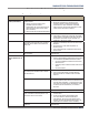
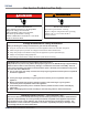
Door Switch Circuit
Perform the following checks if the dishwasher does not
detect the door open or closed. This test will check the wiring
to the door switch and the door switch itself. The following
items are part of the door switch circuit.
n Harness/Connecon
n Door Switch/Latch Assembly
n Control Board
Test Procedure
1. Check for improper installaon of the dishwasher or
leveling. Check door latch mechanism for obstrucons
or binding. Verify door seal is seated properly. Check
for interference between dish racks and door. Repair as
necessary.
2. Unplug dishwasher or disconnect power.
3. Remove the access panel and the
control board cover.
Remove or fold back plasc cover over door switch.
4. Check door switch contacts and all connecons in the
door switch circuit. Visually check that the CN6 connector
on the control and the door latch terminals are securely
installed.
¾ If visual check passes, go to step 5.
¾ If any of the connectors are not inserted properly,
reconnect and retest door latch/switch.
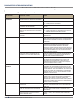
5. Disconnect connector CN6 from the control board.
6. Using an ohmmeter, measure across CN6, pins 1 and
3 (12V & IS respecvely) with the door closed, strike
completely in latch mechanism (switch closed).
¾ If 3 ohms or less is measured, proceed to step 7.
¾ If high resistance is measured when door is closed,
check for loose connecons and repair as needed.
7. Using an ohmmeter, measure across CN6, pins 1 and 3
(12V & IS respecvely) with the door open, strike removed
from latch mechanism (switch open).
¾ If reading is innite, go to step 8.
¾ If reading shows connuity, or door switch is damaged,
replace door switch and retest.
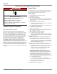
8. Set voltmeter to DC and connect red lead to CN6, pin
1 (12V) and black lead to CN4, pin 2 (DC GND) on the
control board.
9. Plug in dishwasher or reconnect power and with door
open, verify that 12 VDC is present across CN6-1 and CN4-
2.
¾ If 12 VDC is not present, replace the control and retest.
¾ If 12 VDC is present, proceed to step 10.
10. Reconnect CN6 & CN4 to control board and perform
Diagnosc Cycle to verify operaon.
11. Unplug dishwasher or disconnect power.
12. Reassemble all parts and panels.
13. Plug in dishwasher or reconnect power.
DANGER
Electrical Shock Hazard
Only authorized technicians should perform
diagnostic voltage measurements.
After performing voltage measurements,
disconnect power before servicing.
Failure to follow these instructions can result in
death or electrical shock.
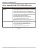
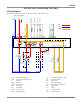
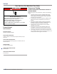
STRIP CIRCUIT - DOOR SWITCH
Figure 1 - Door Switch Strip Circuit
CONTROL BOARD
DOOR SWITCH ASSEMBLY
CONTROL BOARD
TO HEATER
DOOR SWITCH
Heater Relay
CN6-1
CN6-3
TO WASH
PUMP HIGH
TO WASH
PUMP LOW
TO DRAIN
PUMP
Micro PinMicro PinMicro PinMicro Pin
Wash Pump RelayWash Pump RelayDrain Pump Relay
12V
Door Switch
Sensing
Input (IS)
CN5-2
(IS)
PK
PK
IS
(IS)(12V)