
Owner's Manual
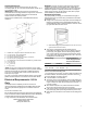
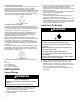
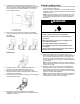
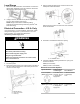


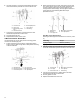


Table Of Contents
- Range Safety
- Self-Cleaning Cycle (on some models)
- General Cleaning
- Tools and Parts
- Location Requirements
- Electrical Requirements - U.S.A. Only
- Unpack Range
- Install Anti-Tip Bracket
- Adjust Leveling Legs
- Level Range
- Electrical Connection - U.S.A. Only
- Verify Anti-Tip Bracket Is Installed and Engaged
- Remove/Replace Drawer
- Oven Door
- Complete Installation

14
6. Use 3/8" nut driver to connect the neutral (white) wire to the
center terminal block post with one of the 10–32 hex nuts.
A. 10–32 hex nut
B. Line 2 (red)
C. Bare (green) ground
wire
D. Ground-link screw
E. Neutral (white) wire
F. Line 1 (black)
G. Terminal lug
7. Connect line 2 (red) and line 1 (black) wires to the outer
terminal block posts with 10-32 hex nuts.
8. Securely tighten hex nuts.
9. Replace terminal block access cover.
3-Wire Connection: Direct Wire
Use this method only if local codes permit connecting ground
conductor to neutral supply wire.
1. Pull the wires through the conduit on cord/conduit plate on
bottom of range. Allow enough slack to easily attach the wiring
to the terminal block.
A. Terminal block
B. Ground-link screw
C. Cord/conduit plate
D. Line 2 (red) wire
E. Bare (green) ground wire
F. Line 1 (black) wire
2. Attach terminal lugs to line 2 (red), bare (green) ground, and
line 1 (black) wires. Loosen (do not remove) the setscrew on
the front of the terminal lug and insert exposed wire end
through bottom of terminal lugs. Securely tighten setscrew to
torque as shown in the following Bare Wire Torque
Specifications chart.
A. Terminal lug
B. Setscrew
C. Line 2 (red) wire
D. Bare (green) ground wire
E. Line 1 (black) wire
Bare Wire Torque Specifications
Attaching terminal lugs to the terminal block - 20 lbs-in. (2.3 N-
m)
Wire Awg Torque
8 gauge copper 25 lbs-in. (2.8 N-m)
6 gauge aluminum 35 lbs-in. (4.0 N-m)
3. Use 3/8" nut driver to connect the bare (green) ground wire to
the center terminal block post with one of the 10–32 hex nuts.
A. 10-32 hex nut
B. Line 2 (red)
C. Ground-link screw
D. Bare (green) ground wire
E. Line 1 (black)
F. Terminal lug
4. Connect line 2 (red) and line 1 (black) wires to the outer
terminal block posts with 10-32 hex nuts.
5. Securely tighten hex nuts.
6. Replace terminal block access cover.