
Owner's Manual
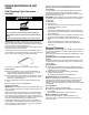
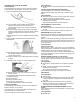
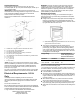
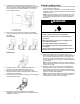
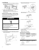
Table Of Contents
- Range Safety
- Self-Cleaning Cycle (on some models)
- General Cleaning
- Tools and Parts
- Location Requirements
- Electrical Requirements - U.S.A. Only
- Unpack Range
- Install Anti-Tip Bracket
- Adjust Leveling Legs
- Level Range
- Electrical Connection - U.S.A. Only
- Verify Anti-Tip Bracket Is Installed and Engaged
- Remove/Replace Drawer
- Oven Door
- Complete Installation

7
Cabinet Dimensions
Cabinet opening dimensions shown are for 25" (64.0 cm)
countertop depth, 24" (61.0 cm) base cabinet depth, and 36" (91.4
cm) countertop height.
IMPORTANT: If installing a range hood or microwave hood
combination above the range, follow the range hood or microwave
hood combination installation instructions for dimensional
clearances above the cooktop surface.
Range may be installed next to combustible walls with zero
clearance.
A. Cabinet door or hinges should not extend into the cutout.
B. 13" (33 cm) max. upper cabinet depth
C. 30" (76.2 cm) min. opening width
D. For minimum clearance to top of cooktop, see NOTE*.
E. 30" (76.2 cm) min. opening width
F. The shaded area is recommended for installation of grounded outlet.
G. 13
1
⁄
8
" (33.3 cm)
H. 7
11
⁄
16
" (19.5 cm)
I. 4
13
⁄
16
" (12.2 cm)
J. 3
11
⁄
16
" (9.4 cm)
*NOTE: 24" (61.0 cm) minimum when bottom of wood or metal
cabinet is shielded by not less than 1/4" (0.64 cm) flame retardant
millboard covered with not less than No. 28 MSG sheet steel,
0.015" (0.4 mm) stainless steel, 0.024" (0.6 mm) aluminum or
0.020" (0.5 mm) copper.
30" (76.2 cm) minimum clearance between the top of the cooking
platform and the bottom of an uncovered wood or metal cabinet.
Electrical Requirements - U.S.A.
Only
If codes permit and a separate ground wire is used, it is
recommended that a qualified electrical installer determine that
the ground path and wire gauge are in accordance with local
codes.
Do not use an extension cord.
Be sure that the electrical connection and wire size are adequate
and in conformance with the National Electrical Code, ANSI/NFPA
70-latest edition and all local codes and ordinances.
A copy of the above code standards can be obtained from:
National Fire Protection Association
1 Batterymarch Park
Quincy, MA 02169-7471
WARNING: Improper connection of the equipment-grounding
conductor can result in a risk of electric shock. Check with a
qualified electrician or service technician if you are in doubt as to
whether the appliance is properly grounded. Do not modify the
power supply cord plug. If it will not fit the outlet, have a proper
outlet installed by a qualified electrician.
Electrical Connection
To properly install your range, you must determine the type of
electrical connection you will be using and follow the instructions
provided for it here.
� Range must be connected to the proper electrical voltage and
frequency as specified on the model/serial/rating plate. The
model/serial/rating plate is located behind the oven door on the
top right-hand side of the oven frame.
A. Model/serial/rating plate (located behind the oven door on the top
right-hand side of the oven frame)
� This range is manufactured with the neutral terminal
connected to the cabinet. Use a 3-wire, UL listed, 40 or 50 A
power supply cord (pigtail). See the following Range Rating
chart. If local codes do not permit ground through the neutral,
use a 4-wire power supply cord rated at 250 V, 40 or 50 A and
investigated for use with ranges.
Range Rating* Specified Rating of
Power Supply Cord Kit
and Circuit Protection
120/240 V 120/208 V Amps
8.8 - 16.5 kW 7.8 - 12.5 kW 40 or 50**
16.6 - 22.5 kW 12.6 - 18.5 kW 50
* The NEC calculated load is less than the total connected load
listed on the model/serial/rating plate.
** If connecting to a 50 A circuit, use a 50 A rated cord with kit. For
50 A rated cord kits, use kits that specify use with a nominal 1
3
/
8
"
(34.9 mm) diameter connection opening.
� A circuit breaker is recommended.
� The range can be connected directly to the circuit breaker box
(or fused disconnect) through flexible or nonmetallic sheathed,
copper or aluminum cable. See the "Electrical Connection - U.
S.A. Only" section.
� Allow at least 6 ft (182.9 cm) of slack in the line so that the
range can be moved if servicing is ever necessary.
� A UL Listed conduit connector must be provided at each end of
the power supply cable (at the range and at the junction box).
� Wire sizes and connections must conform with the rating of the
range.