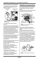
FOR SERVICE TECHNICIAN ONLY - DO NOT REMOVE OR DESTROY IMPORTANT Electrostatic Discharge (ESD) Sensitive Electronics ESD problems are present everywhere. ESD may damage or weaken the machine control electronics.The new control assembly may appear to work well after repair is finished, but failure may occur at a later date due to ESD stress. ■ Use an anti-static wrist strap. Connect wrist strap to green ground connection point or unpainted metal in the appliance.
FOR SERVICE TECHNICIAN ONLY - DO NOT REMOVE OR DESTROY ACTIVATING THE DIAGNOSTIC TEST MODE 1. Be sure the dryer is not currently running a cycle (the in-progress screen should not be displayed). 2. From the perimeter of the LCD, select the Sound and Display option. a. Make sure that sound volume level is on “High”. b. Select “Sales and Service Mode” from the available options on the LCD. c. Select “Enter Password”, then press 5, 6, 5, 6 within 5 seconds. d.
FOR SERVICE TECHNICIAN ONLY - DO NOT REMOVE OR DESTROY DIAGNOSTIC: Displaying Inlet Air Flow (Electric Models Only) Used to display the air flow value at the inlet of the heater box being measured by the machine control. After entering the Diagnostic Test Mode and selecting the Component Activation option, press the “Air Flow” button and “Ok” to enter the Inlet Air Flow Test; press “Start” to begin the test. A 30 or 50 second countdown timer will start and the dryer will turn on.
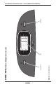
PAGE 4 Figure 1. Console Diagnostics.
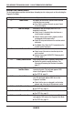
FOR SERVICE TECHNICIAN ONLY - DO NOT REMOVE OR DESTROY DISPLAY FAULT/ERROR CODES The fault codes below would be indicated when attempting to start a drying cycle, or after activating the Diagnostic Test Mode. Display pf l2 af f:0 1 f:02 f:20 f:22 f:23 f:24 Description Power Failure Explanation/Recommended Procedure PF displays to indicate that a power failure occurred while the dryer was running. ■ Press Start to continue the cycle, or press Cancel to clear the display.
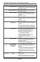
FOR SERVICE TECHNICIAN ONLY - DO NOT REMOVE OR DESTROY Display f:25 Description Inlet Thermistor Shorted Explanation/Recommended Procedure F:25 displays if the inlet thermistor is shorted. This fault code appears ONLY when in the Diagnostic Test Mode. ■ See TEST #4a, page 13. f:26 Motor Drive System Failure F:26 displays if there is a motor drive system failure. ■ See TEST #3, page 10. f:28 Moisture Sensor Open F:28 displays if the moisture sensor strip is open.
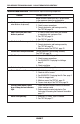
FOR SERVICE TECHNICIAN ONLY - DO NOT REMOVE OR DESTROY TROUBLESHOOTING GUIDE Some tests will require accessing components. Problem Won’t power up. (No response when buttons are pressed.) Won’t start cycle when Start button is pressed. Won’t shut off when expected. Control won’t accept selections. Won’t heat. Heats in air cycle. Shuts off before clothes are dry. Pushing Power button causes dryer to beep, but no indicators light. Water not dispensing.
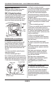
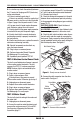
FOR SERVICE TECHNICIAN ONLY - DO NOT REMOVE OR DESTROY TROUBLESHOOTING TESTS NOTE: These checks are done with the dryer unplugged or disconnected from power. TEST #1 Supply Connections This test assumes that proper voltage is present at the outlet, and for U.S. installations, a visual inspection indicates that the power cord is securely fastened to the terminal block (electric dryer) or wire harness connection (gas dryer). Remove Screw Cover Plate Figure 2. Remove the cover plate. ELECTRIC DRYER (U.S.
FOR SERVICE TECHNICIAN ONLY - DO NOT REMOVE OR DESTROY 4. With an ohmmeter, check the continuity from L1 and N plug terminals of the power cord to the terminals for L1 and N on the machine control electronics. See figure 3b. Power Cord Plug Machine Control Electronics P9 N Neu L1 1 GAS DRYER (U.S. and Canadian Installations): 1. Unplug dryer or disconnect power. 2. Remove the cover plate from the top right corner of the back of the dryer. See figure 2, page 8. 3.
FOR SERVICE TECHNICIAN ONLY - DO NOT REMOVE OR DESTROY 6. In a similar way, check the continuity between the L1 terminal of the plug and P9-2 (black wire) on the control board. If there is continuity, go to step 8. If there is no continuity, check the continuity of the power cord in a similar way to that illustrated in figure 5, page 9, but for power cord’s L1 wire. If an open circuit is found, replace the power cord. Otherwise, replace the main harness. 7.
FOR SERVICE TECHNICIAN ONLY - DO NOT REMOVE OR DESTROY Main Winding: Lt. Blue Wire in Back and Bare Copper Wire 5 1 26 4 3 Start Winding: Lt. Blue Wire in Back and Bare Copper Wire Lt. Blue Wires Belt Switch Pulley 5 1 26 4 3 6. Remove the bare copper wire terminal from pin 5 of black drive motor switch. See figure 8. Belt Switch Figure 9. Checking the belt switch. Figure 8. Main and start winding measure points. 7.
FOR SERVICE TECHNICIAN ONLY - DO NOT REMOVE OR DESTROY Replace the heater if it is electrically open. Replace both the thermal cut-off and inlet thermistor/high limit thermostat assembly if either the thermal cut-off or the high limit thermostat is electrically open. Inlet Thermistor/High Limit Thermostat Assembly Heater Element Thermal Cut-Off Thermal Fuse Outlet Thermistor Electric Dryer High Limit Thermostat Thermal Cut-Off Flame Sensor 5.
FOR SERVICE TECHNICIAN ONLY - DO NOT REMOVE OR DESTROY TEST #4a Thermistors Outlet Thermistor The machine control electronics monitors the exhaust temperature using the outlet thermistor, and cycles the heater relay on and off to maintain the desired temperature. Begin with an empty dryer and a clean lint screen. 1. Plug in dryer or reconnect power. 2. Start the Timed Dry cycle. 3.
FOR SERVICE TECHNICIAN ONLY - DO NOT REMOVE OR DESTROY Inlet Thermistor (Electric Dryers) The machine control electronics monitors the inlet temperature using an inlet thermistor that is part of the high limit thermostat assembly. 1. Activate the Diagnostic Test Mode. See procedure on page 1. 2. If f:24 or f:25 is a displayed error in the Diagnostic Test Mode, the inlet thermistor or wire harness is either open or shorted. Unplug dryer or disconnect power.
FOR SERVICE TECHNICIAN ONLY - DO NOT REMOVE OR DESTROY TEST #4d Gas Valve, Gas Dryer 1. Unplug dryer or disconnect power. 2. Access the gas valve. 3. Use an ohmmeter to determine if a gas valve coil has failed. Remove harness plugs. Measure resistance across terminals. Readings should match those shown in the following chart. If not, replace coil. Terminals 1 to 2 1 to 3 4 to 5 IMPORTANT: Be sure all harness wires are looped back through the strain relief after checking or replacing coils.
FOR SERVICE TECHNICIAN ONLY - DO NOT REMOVE OR DESTROY 7. Measure the resistance across each of the outermost contacts and the center terminal (ground connection). If a resistance less than infinity is measured, replace the sensor harness. 8. If moisture sensor diagnostic test passes, check the thermistor: Perform TEST #4a, pages 13–14. If the problem persists after replacing the moisture sensor and thermistor, replace the machine control electronics. 2. Plug in dryer or reconnect power. 3.
FOR SERVICE TECHNICIAN ONLY - DO NOT REMOVE OR DESTROY 6. Plug in dryer or reconnect power. 7. Activate the Diagnostic Test Mode, page 2, and check to make sure water is being sprayed into the drum. 8. If water is still not dispensed: Unplug dryer or disconnect power. Replace the machine control electronics. TEST #8 Water Valve Activate the Diagnostic Test Mode as shown on page 2. Press Start and verify that water is being sprayed in the drum. See figure 13.
FOR SERVICE TECHNICIAN ONLY - DO NOT REMOVE OR DESTROY CALIBRATING THE TOUCH SCREEN If you are having difficulty selecting or dragging the correct icons with the touch screen, for example, if you touch one icon but one adjacent to it is selected instead, the touch screen may need calibration. To calibrate: 1. Touch the Sound & Display button to access the Sound & Display preferences. 2. Select Screen Calibration. 3. Follow the on-screen instructions to calibrate the touch screen.
BK USB J600 USER INTERFACE FASCIA ASSY P4-10 WPL# W10280760 BK BK P4-9 P4-7 P4-8 P4-6 POWER CUBE MIST VALVE LED SPEAKER P4-11 P4-4 BK/WH P4-12 P4-5 P1-1 P1-3 P2-1 L1 LINE - BK P4-1 PAGE 19 P4-2 P2-2 } HEATER RELAY 1 P2-1 VDD P2-2 DATA P2-3 VSS SERIAL COM R MACHINE CONTROL ELECTRONICS HEATER RTN 2 3 4 COM R (0.25 TERMINAL) J2 L1 MIST HEATER +V WIDE ISO BOARD J1 P8-1 P9-2 N.O. (0.25 TERMINAL) 5 4 3 1 R THERMAL CUT-OFF INLET TEMP RTN INLET TEMP.
BK USB J600 USER INTERFACE FASCIA ASSY P4-10 WPL# W10280760 BK BK BK/WH P4-9 P4-7 P4-8 P4-6 POWER CUBE MIST VALVE LED SPEAKER P4-11 P4-4 P2-2 P4-12 P4-5 L1 LINE - BK P4-1 PAGE 20 P4-2 P1-1 P1-3 P2-1 R WIDE ISO BOARD J2 P8-1 P9-2 2 3 4 } SERIAL COM MACHINE CONTROL ELECTRONICS TF2 HEATER RTN HEATER +V R-W HEATER RELAY 1 P2-1 VDD P2-2 DATA P2-3 VSS L1 MIST THERMAL FUSE TF1 N.O. (0.25 TERMINAL) COM (0.25 TERMINAL) 5 4 3 1 J1 R GAS DRYER WIRING DIAGRAM (U.S.
BK N * LED DEL P4-9 P4-7 P4-8 SPEAKER HAUTPARLEUR P8-1 J2 P9-2 3 2 3 4 HEATER RTN RET. CHAUFFAGE HEATER +V ÉLÉMENT CHAUFFANT +V MOIST. RTN RET. HUMIDITÉ MOIST.
* WPL# W10280760 USB LED DEL P4-9 P4-7 P4-8 SPEAKER HAUTPARLEUR J1 P8-1 J2 P9-2 N.O. 2 3 4 COM. SÉRIELLE *SERIAL COM HEATER +V CHAUFFAGE +V HEATER RELAY 1 RELAIS CHAUFFAGE–1 P2-1 VDD P2-2 DATA P2-3 VSS MIST BRUME L1 R R TF1 HEATER RTN RET. CHAUFFAGE (0.25 TERMINAL) R R COM (0.25 TERMINAL) 3 WIDE ISO BOARD 4 CARTE D’ISO LARGE 5 1 R R TF2 R-W R-BL N.C. P.C. N.C. P.C. TEMP. TEMP. TEMP. RTN TEMP. RETOUR MODEL MODÈLE MODEL RTN RET. MODÈLE MOIST. RTN RET. HUMIDITÉ MOIST.
POUR LE TECHNICIEN SEULEMENT - NE PAS ENLEVER NI DÉTRUIRE IMPORTANT Circuits électroniques sensibles aux décharges électrostatiques Le risque de décharge électrostatique est permanent; une décharge électrostatique peut détériorer ou détruire les circuits électroniques de la machine. La nouvelle carte peut donner l’impression qu’elle fonctionne correctement après la réparation, mais une décharge électrostatique peut lui avoir fait subir des dommages qui provoqueront une défaillance plus tard.
POUR LE TECHNICIEN SEULEMENT - NE PAS ENLEVER NI DÉTRUIRE ■ ■ ■ La corrosion des pièces de connexion est une cause potentielle d’anomalie de fonctionnement des organes de commande. Inspecter visuellement les connexions et contrôler la continuité des circuits avec un ohmmètre. Connecteurs : Examiner le sommet d’un connecteur. Rechercher conducteurs brisés ou mal connectés. Un conducteur peut être insuffisamment enfoncé pour qu’il puisse avoir un bon contact sur la broche métallique.
POUR LE TECHNICIEN SEULEMENT - NE PAS ENLEVER NI DÉTRUIRE DIAGNOSTIC : Contacteur de la porte L’ouverture de la porte doit entraîner l’émission d’un son et l’affichage du texte suivant au centre de l’écran ACL : “Door Open” (porte ouverte). Si l’ouverture de la porte n’entraîne pas l’émission d’un son et l’affichage de “Door Open” (porte ouverte), passer à TEST no 7, page 40.
POUR LE TECHNICIEN SEULEMENT - NE PAS ENLEVER NI DÉTRUIRE Pour des débits d’air inférieurs à 29 pi³/min, “Air Flow < 29” (débit d’air < 29) s’affiche. Si le débit d’air est faible (inférieur à 29 pi³/ min), vérifier que le tamis à charpie est propre, que le joint de porte est en place et que la bouche de décharge n’est pas obstruée.
PAGE 27 Figure 1. Diagnostic de la console.
POUR LE TECHNICIEN SEULEMENT - NE PAS ENLEVER NI DÉTRUIRE CODES D’ANOMALIE/ERREUR Les codes d’anomalie ci-dessous sont normalement affichés lors d’une tentative de mise en marche d’un programme de séchage, ou après l’activation du Mode de test de diagnostic. Affichage pf l2 af f:0 1 f:02 f:20 f:22 f:23 f:24 Description Panne de courant Explications et opérations recommandées PF affiche pour indiquer qu’une panne de courant est survenue durant le fonctionnement de la sécheuse.
POUR LE TECHNICIEN SEULEMENT - NE PAS ENLEVER NI DÉTRUIRE Affichage f:25 f:26 f:28 f:29 f:30 f:3 1 f:50 f:70 ou f:7 1 Description Thermistance d’entrée court-circuitée Explications et opérations recommandées F:25 affiche si le circuit de la thermistance comporte un court-circuit. Ce code d’anomalie apparaît SEULEMENT lorsque le mode de test de diagnostic est actif. ■ Voir TEST no 4a, page 36.
POUR LE TECHNICIEN SEULEMENT - NE PAS ENLEVER NI DÉTRUIRE Affichage f:72 à f:78 Description Défaillance du module électronique de la console Explications et opérations recommandées F:72 à F:78 affiche en présence d’une défaillance du module électronique de la console. ■ Remplacer le module électronique de la console. Voir Modules électroniques – Accès et dépose, page 41. GUIDE DE DÉPANNAGE Certains tests nécessitent l’accès aux composants. Problème Pas de mise en marche.
POUR LE TECHNICIEN SEULEMENT - NE PAS ENLEVER NI DÉTRUIRE TESTS DE DÉPANNAGE NOTE : La sécheuse doit être débranchée ou déconnectée de la source d’alimentation électrique pour l’exécution de ces contrôles. TEST No 1 Connexions d’alimentation Pour ce test, on suppose que la tension appropriée est disponible sur la prise de courant. Ôter la vis Couvercle Figure 2. Enlever le couvercle. SÉCHEUSE ÉLECTRIQUE : 1. Débrancher la sécheuse ou déconnecter la source de courant électrique. 2.
POUR LE TECHNICIEN SEULEMENT - NE PAS ENLEVER NI DÉTRUIRE 3. Vérifier que le cordon d’alimentation est correctement raccordé au câblage de la sécheuse. Voir figure 4. Câblage Cordon d’alimentation Figure 4. Raccordement entre cordon d’alimentation et câblage de la sécheuse (sécheuse à gaz). 4. Accéder au module électronique de commande de la machine sans débrancher de conducteurs sur la carte des circuits de commande. 5.
POUR LE TECHNICIEN SEULEMENT - NE PAS ENLEVER NI DÉTRUIRE 3. Débrancher la sécheuse ou déconnecter la source de courant électrique. 4. Remplacer le module de commande électronique de la machine. 5. Brancher la sécheuse ou reconnecter la source de courant électrique. 6. Exécuter les étapes du processus du mode de test de diagnostic manuel, page 24, pour vérifier le résultat de la réparation. Poulie de tensionnement TEST No 3 Circuits du moteur Courroie du tambour Figure 6.
7. Consulter la figure 8, page 33. Mesurer les valeurs de résistance des bobinages du moteur (bobinage principal et bobinage de démarrage). Voir le tableau suivant. NOTE : On doit contrôler les bobinages principal et de démarrage sur le moteur. Résistance Points Bobinage Ω de mesure Conducteur bleu clair à l’arrière sur broche 4, Principal 3,3–3,6 et conducteur de cuivre nu déconnecté de la broche 5 du contacteur noir du moteur d’entraînement.
POUR LE TECHNICIEN SEULEMENT - NE PAS ENLEVER NI DÉTRUIRE Si la résistance est d’environ 10 Ω, passer à l’étape 5. S’il y a un circuit ouvert, passer à l’étape 4. 4. Inspecter visuellement les connexions des conducteurs sur le coupe-circuit thermique, le thermostat de température maximum et l’élément chauffant. Si les connexions sont en bon état, contrôler la continuité à travers chacun de ces composants. Remplacer l’élément chauffant s’il est affecté par un circuit ouvert.
POUR LE TECHNICIEN SEULEMENT - NE PAS ENLEVER NI DÉTRUIRE Impossibilité d’arrêt du chauffage : 1. Débrancher la sécheuse ou déconnecter la source de courant électrique. 2. Accéder au module de commande électronique de la machine. Voir Modules électroniques – Accès et dépose, page 41. TOUTES LES SÉCHEUSES : Débrancher le connecteur P14 et mesurer la résistance entre P14-3 (conducteur rouge) et P14-6 (conducteur rouge) au connecteur.
POUR LE TECHNICIEN SEULEMENT - NE PAS ENLEVER NI DÉTRUIRE RÉSISTANCE DE LA THERMISTANCE DU CIRCUIT DE DÉCHARGE Temp Résistance Temp Résistance °C (°F) kΩ °C (°F) kΩ 10° (50°) 19,0–22,0 27° (80°) 8,5–10,5 16° (60°) 14,8–16,8 32° (90°) 6,8–8,8 21° (70°) 11,5–13,5 38° (100°) 5,0–7,0 Si la résistance de la thermistance ne correspond pas aux valeurs indiquées dans le tableau, remplacer la thermistance du circuit de décharge.
POUR LE TECHNICIEN SEULEMENT - NE PAS ENLEVER NI DÉTRUIRE TEST No 4c Coupe-circuit thermique Si la sécheuse ne produit pas de chaleur, contrôler l’état du coupe-circuit thermique. 1. Débrancher la sécheuse ou déconnecter la source de courant électrique. 2. Accéder au coupe-circuit thermique. 3. À l’aide d’un ohmmètre, contrôler la continuité à travers le coupe-circuit thermique; voir sa position à la figure 10, page 35. 4.
POUR LE TECHNICIEN SEULEMENT - NE PAS ENLEVER NI DÉTRUIRE 4. Accéder au module de commande électronique de la machine. Voir Modules électroniques – Accès et dépose à la page 41. Débrancher le connecteur P13 de la carte des circuits. Vérifier les connexions du câblage principal entre le câblage du capteur et le module de commande de la machine pour voir s’il y a un court-circuit ou un circuit ouvert. Remplacer le câblage principal si nécessaire. Si le câblage est en bon état, poursuivre avec l’étape 5.
POUR LE TECHNICIEN SEULEMENT - NE PAS ENLEVER NI DÉTRUIRE TEST No 7 Contacteur de la porte Buse d’injection d’eau Voir à la page 24 et exécuter les étapes du processus de Activation du mode test de diagnostic, puis exécuter les étapes du processus de DIAGNOSTIC : Contacteur de porte, page 25. L’émission d’un signal sonore lors de chaque manoeuvre de fermeture ou d’ouverture de la porte vérifie la fonctionnalité du contacteur; et le message de statut de la porte apparaît sur l’afficheur.
POUR LE TECHNICIEN SEULEMENT - NE PAS ENLEVER NI DÉTRUIRE 6. Brancher la sécheuse ou reconnecter la source de courant électrique. 7. Accéder au mode “Activation du mode test de diagnostic” présenté à la page 24; vérifier l’injection d’eau dans le tambour. 8. S’il n’y a toujours pas d’introduction d’eau : Débrancher la sécheuse ou déconnecter la source de courant électrique. Remplacer le module de commande électronique de la machine. Dépose de module de l’interface-utilisateur 2.
POUR LE TECHNICIEN SEULEMENT - NE PAS ENLEVER NI DÉTRUIRE Calibrage de l’écran tactile Si vous avez des difficultés à sélectionner ou à faire glisser les bonnes icônes avec l’écran tactile – par exemple, si vous appuyez sur une icône mais que c’est l’icône située à côté d’elle qui est sélectionnée à la place, l’écran tactile doit peut-être être calibré. Calibrage : 1. Appuyer sur le bouton Sound & Display (Son et affichage) pour accéder aux préférences de son et affichage. 2.
BK N * LED DEL P4-9 P4-7 P4-8 SPEAKER HAUTPARLEUR P8-1 J2 P9-2 3 2 3 4 HEATER RTN RET. CHAUFFAGE HEATER +V ÉLÉMENT CHAUFFANT +V MOIST. RTN RET. HUMIDITÉ MOIST.
* WPL# W10280760 USB LED DEL P4-9 P4-7 P4-8 SPEAKER HAUTPARLEUR J1 P8-1 J2 P9-2 N.O. 2 3 4 COM. SÉRIELLE *SERIAL COM HEATER +V CHAUFFAGE +V HEATER RELAY 1 RELAIS CHAUFFAGE–1 P2-1 VDD P2-2 DATA P2-3 VSS MIST BRUME L1 R R TF1 HEATER RTN RET. CHAUFFAGE (0.25 TERMINAL) R R COM (0.25 TERMINAL) 3 WIDE ISO BOARD 4 CARTE D’ISO LARGE 5 1 R R TF2 R-W R-BL N.C. P.C. N.C. P.C. TEMP. TEMP. TEMP. RTN TEMP. RETOUR MODEL MODÈLE MODEL RTN RET. MODÈLE MOIST. RTN RET. HUMIDITÉ MOIST.