
Installation Guide


16
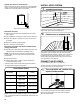
VENTING REQUIREMENTS
WARNING: To reduce the risk of re, this dryer MUST BE
EXHAUSTED OUTDOORS.
IMPORTANT: Observe all governing codes and ordinances.
Dryer exhaust must not be connected into any gas vent,
chimney, wall, ceiling, attic, crawlspace, or a concealed space
of a building. Only rigid or exible metal vent shall be used for
exhausting.
4"
(102 mm)
4" (102 mm) heavy metal exhaust vent
■ Only a 4" (102 mm) heavy metal exhaust vent and clamps
may be used.
■ Do not use plastic or metal foil vent.
Rigid metal vent:
■ Recommended for best drying performance and to avoid
crushing and kinking.
Flexible metal vent: (Acceptable only if accessible to clean)
■ Must be fully extended and supported in nal dryer location.
■ Remove excess to avoid sagging and kinking that may
result in reduced airow and poor performance.
■ Do not install in enclosed walls, ceilings, or oors.
■ The total length should not exceed 7
3
/
4
ft. (2.4 m).
■ The length of exible metal vent used must be included in
the overall vent system design as shown in the “Vent System
Charts.”
NOTE: If using an existing vent system, clean lint from
entire length of the system and make sure exhaust hood
is not plugged with lint. Replace plastic or metal foil vents
with rigid metal or exible metal vents. Review Vent System
Chart and if necessary, modify existing vent system to
achieve best drying performance.
VENTING
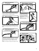
Connect gas supply to dryer
1.
Remove red cap from gas pipe. Using a wrench to tighten,
connect gas supply to dryer. Use pipe-joint compound
on threads of all non-ared male ttings. If exible metal
tubing is used, be sure there are no kinks.
NOTE: For LP gas connections, you must use pipe-joint
compound resistant to action of LP gas. Do not use
TEFLON
®†
tape.
A
B
Non-ared
male tting
Flared
male tting
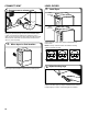
Open shut-off valve
3.
Open shut-off valve in supply line; valve is open when handle
is parallel to gas pipe. Then, test all connections by brushing
on an approved noncorrosive leak-detection solution.
Bubbles will show a leak. Correct any leaks found.
A
B
Open valve
Closed valve
B
A
D
C
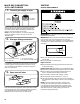
Plan pipe tting connection
2.
A combination of pipe ttings must be used to connect dryer
to existing gas line. A recommended connection is shown.
Your connection may be different, according to supply line
type, size, and location.
A. 3/8" exible gas connector
B. 3/8" dryer pipe
C. 3/8" to 3/8" pipe elbow
D. 3/8" pipe-to-are adapter tting
MAKE GAS CONNECTION -
U.S.A. AND CANADA