ELECTRONIC ELECTRIC DRYER For questions about features, operation/performance, accessories or service, call: 1-800-253-1301 parts, or visit our website at... www.whidpooLcom Table of Contents ....................................................
TABLEOF CONTENTS DRYER SAFETY .............................................................................. INSTALLATION INSTRUCTIONS .................................................. Tools and Parts ............................................................................ Optional Pedestal ......................................................................... Location Requirements ................................................................ Electrical Requirements ..............................
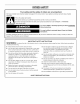
DRYERSAFETY Your safety and the safety of others are very important. We have provided many important safety messages in this manual and on your appliance. Always read and obey all safety messages. This is the safety alert symbol. This symbol alerts you to potential hazards that can kill or hurt you and others. All safety messages will follow the safety alert symbol and either the word "DANGER" or "WARNING.
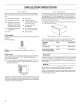
INSTALLATION INSTRUCTIONS Gather the required tools and parts before starting installation. Read and follow the instructions provided with any tools listed here. • Flat-blade screwdriver • Vent clamps • #2 Phillips screwdriver • • Adjustable wrench that opens to 1" (2.
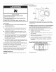
Dryer Dimensions 36" (91.4 cm) Explosion Hazard Keep flammable materials and vapors, such as gasoline, away from dryer, Place dryer at least 18 inches (46 cm) above the floor for a garage installation. Failure to do so can result in death, explosion, cm), • A separate 30-amp circuit. • If you are using a power cord, a grounded electrical outlet located within 2 ft (61 cm) of either side of the dryer. See "Electrical Requirements." • A sturdy floor to support the total dryer weight of 127 Ibs (57.
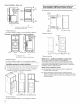
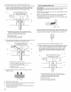
Closet installation - Dryer only Recommended installation spacing for recessed or closet installation, with stacked washer and dryer The dimensions shown are for the recommended 48 in.2 * {310 cm 2) spacing. 2L 3"* (7.6 cm) 24 in?* .._ 3"* (155crn2) '--_ (7.6 crn) I1"*1<-28.6s"÷1 s"**l (2.5 crn) (72.77 crn)(12.7 crn) A 2L B A. Side view - closet or confined area B. Closet door with vents 24 in. 2 * {155 crn2) *Required spacing **For side or bottom venting, 0" (0 cm) spacing is allowed.
It is your responsibility [] To contact a qualified electrical installer. [] To be sure that the electrical connection is adequate and in conformance with the National Electrical Code, ANSl/NFPA 70-latest edition and all local codes and ordinances. The National Electric Code requires a 4-wire supply connection for homes built after 1996, dryer circuits involved in remodeling after 1996, and all mobile home installations.
Direct Wire Power Supply Cord Fire Hazard Fire Hazard Use a new UL listed 30 amp power supply cord. Use 10 gauge solid copper Use a UL listed strain relief. Use a UL listed strain Disconnect power before making Disconnect electrical connections. Connect remaining 2 terminals (gold). Securely tighten Connect remaining 2 terminals (gold). Securely tighten connections. Failure to de so can result in death, fire, or electrical shock. 1. 2. Disconnect power.
Put power supply cord through the strain relief. Be sure that the wire insulation on the power supply cord is inside the strain relief. The strain relief should have a tight fit with the dryer cabinet and be in a horizontal position. Do not further tighten strain relief screws at this point.
1= 2. Remove center silver-colored terminal block screw. Remove neutral ground wire from external ground conductor screw. Connect neutral ground wire and the neutral wire (white or center wire) of power supply cord under center, silver-colored terminal block screw. Tighten screw. 4-wire connection: Direct wire IMPORTANT: A 4-wire connection is required for mobile homes and where local codes do not permit the use of 3-wire connections. Direct wire cable must have 5 ft (1.
3. Connect ground wire (green or bare) of direct wire cable to external ground conductor screw. Tighten screw. 1. 2. Loosen or remove center silver-colored terminal block screw. Connect neutral wire (white or center wire) of power supply cord to the center, silver-colored terminal screw of the terminal block. Tighten screw. D A. External ground conductor 4. screw B. Ground wire (green or bare) of power supply cable C. 3/4"(1.9 cm) UL listed strain relief D.
3. 3-wire connection: Direct wire Use where local codes permit connecting conductor to neutral wire. cabinet-ground Place the hooked ends of the other direct wire cable wires under the outer terminal block screws (hooks facing right). Squeeze hooked ends together. Tighten screws. !! !! Direct wire cable must have 5 ft (1.52 m) of extra length so dryer can be moved if needed. Strip 31/2'' (8.9 cm) of outer covering from end of cable. Strip insulation back 1" (2.5 cm).
Rigid metal vent • For best drying performance, recommended. rigid metal vents are • Rigid metal vent is recommended kinking. to avoid crushing and Flexible metal vent • Flexible metal vents are acceptable cleaning. • Flexible metal vent must be fully extended and supported when the dryer is in its final location. • Remove excess flexible metal vent to avoid sagging and kinking that may result in reduced airflow and poor performance.
An exhaust hood should cap the vent to keep rodents and insects from entering the home. Exhaust hood must be at least 12" (30.5 cm) from the ground or any object that may be in the path of the exhaust (such as flowers, rocks or bushes, snow line, etc.). Do not use an exhaust hood with a magnetic latch. Improper venting can cause moisture and lint to collect indoors, which may result in: [] Moisture damage to woodwork, carpets, etc. [] Housecleaning A B C A.
Determine vent path • Select the route that will provide the straightest direct path outdoors. and most • Plan the installation turns. • When using elbows or making turns, allow as much room as possible. • Bend vent gradually to avoid kinking. • Use the fewest 90 ° turns possible. to use the fewest number of elbows and 1. 2. 3. Install exhaust hood. Use caulking compound to seal exterior wall opening around exhaust hood. Connect vent to exhaust hood. Vent must fit inside exhaust hood.
1. Using a 4" (10.2 cm) clamp, connect vent to exhaust outlet in dryer. If connecting to existing vent, make sure the vent is clean. The dryer vent must fit over the dryer exhaust outlet and inside the exhaust hood. Make sure the vent is secured to exhaust hood with a 4" (10.2 cm) clamp. 2. Move dryer into its final location. Do not crush or kink vent. 3. (On gas models) Make sure that there are no kinks in the flexible gas line. 4. Once the exhaust vent connection corner posts and cardboard.
2= Reverse the strike Remove hinge cover. 1. 2. Use a small flat-blade screwdriver to remove plug strip from the dryer door opening. Slide the head of the screwdriver under the plugs, being certain not to scratch the dryer surface. Lift up. Remove the strike. 3. Insert strike and plug strip on the opposite side. A ................... __ A. Door hinge B. Plug strips C. Hinge cover 3= Remove the 4 screws that attach to the inner door hinge and move the hinge to the other side.
1. Check that all parts are now installed. If there is an extra part, go back through the steps to see which step was skipped. 2. Check that you have all of your tools. If the dryer will not start, check the following: 3. Dispose of/recycle all packaging • Controls are set in a running or "On" position. 4. Check the dryer's final location. Be sure the vent is not crushed or kinked. • Start button has been pushed firmly. • Dryer is plugged into an outlet and/or electrical supply is connected.
DRYERUSE Explosion Hazard Keep flammable materials and vapors, such as gasoline, away from dryer. Do not dry anything that has ever had anything flammable on it (even after washing). Failure to follow these instructions explosion, or fire. can result in death, WARNING: To reduce the risk of fire, electric shock, or injury to persons, read the IMPORTANT SAFETY INSTRUCTIONS before operating this appliance. Follow these basic steps to start your dryer.
NOTE: Dryness level selections can be made only while using Auto Cycles. Selecting More Dry, Normal or Less Dry automatically adjusts the sensed time needed. This feature allows you to lock your settings to avoid unintended use of the dryer. You can also use the control lock feature to avoid unintended cycle or option changes during dryer operation. To enable the control lock feature: MOREDRY NORMAL Press and hold END OF CYCLE SIGNAL button for 3 seconds.
You may follow the progress of your dryer with the drying Status indicator lights. Select the drying cycle that matches the type of load you are drying. See Auto Preset or Manual Preset Cycle Settings charts. SENSING CASU WET::/ DELICATE : ..... SUPER/ _XTOUCH DAMP'/ DELICATE/ _ COOLDOWN:_/ DAMP_ DRY_ CYCLE COMPLETE _/ \\ \\ _ \\\UP /I X// |QUICK ]DRY WRINKLE SHIELD Sensing When a cycle is first turned on, the SENSING light illuminates until a wet item is detected.
Auto Preset Cycle Settings Auto Cycles Load Type Temp. Time* (Minutes) HEAVY DUTY Heavyweight, towels High 40 NORMAL Mixed loads, corduroys, work clothes, sheets Medium 35 CASUAL Permanent press, synthetics Low 35 DELICATE Lightweight synthetics Low 30 Extra Low 25 DAMP DRY Clothes to come out suitable for ironing Low 20 SHIELD TM Feature The WRINKLE SHIELD TM feature helps smooth out wrinkles that form when you cannot unload the dryer promptly at the end of a cycle.
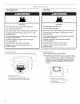
End of Cycle Signal The End of Cycle Signal produces an audible sound when the drying cycle is finished, Promptly removing clothes at the end of the cycle reduces wrinkling. 1. Open dryer door. ON ! ENDOF I CYCLE SIGNAL I A. Front edge Hold 3 secondsto _1 Place drying rack inside dryer drum, positioning the back wire on the ledge of the inner dryer back panel. Push down on front edge of drying rack to secure over the lint screen. 2.
DRYERCARE ,. ............. _=_............. ° .......I.(_(;III01 Keep dryer area clear and free from items that would obstruct the flow of combustion and ventilation air. As needed cleaning Laundry detergent and fabric softener residue can build up on the lint screen. This buildup can cause longer drying times for your clothes, or cause the dryer to stop before your load is completely dry. The screen is probably clogged if lint falls off while the screen is in the dryer.
Moving From Inside the Dryer Cabinet Lint should be removed every 2 years, or more often, depending on dryer usage. Cleaning should be done by a qualified person. From the Exhaust Vent care For power supply cord-connected 1. Unplug the power supply cord. dryers: 2. Make sure leveling legs are secure in dryer base. 3. Use masking tape to secure dryer door. Lint should be removed every 2 years, or more often, depending on dryer usage. Vacation care Operate your dryer only when you are at home.
Is the dryer located in a closet? Closet doors must have ventilation openings at the top and bottom of the door. The front of the dryer requires a minimum of 1" (2.5 cm) of airspace, and, for most installations, the rear of the dryer requires 5" (12.7 cm). See "Installation Instructions." Clothes are not drying satisfactorily, drying times are too long, or load is too hot • Is the lint screen clogged with lint? Lint screen should be cleaned before each load.
ASSISTANCEOR SERVICE Before calling for assistance or service, please check "Troubleshooting." It may save you the cost of a service call. If you still need help, follow the instructions below. Whirlpool designated service technicians are trained to fulfill the product warranty and provide after-warranty service, anywhere in the United States. When calling, please know the purchase date and the complete model and serial number of your appliance.
WHIRLPOOLCORPORATIONMAJORAPPLIANCEWARRANTY ONE YEAR LIMITED WARRANTY For one year from the date of purchase, when this major appliance is operated and maintained according to instructions attached to or furnished with the product, Whirlpool Corporation or Whirlpool Canada LP (hereafter "Whirlpool") will pay for FSP _ replacement parts and repair labor to correct defects in materials or workmanship. Service must be provided by a Whirlpool designated service company. ITEMS WHIRLPOOL WILL NOT PAY FOR 1.