DRYER SAFETY Your safety and the safety of others are very important. We have provided many important safety messages in this manual and on your appliance. Always read and obey all safety messages. This is the safety alert symbol, This symbol alerts you to potential hazards that can kill or hurt you and others. All safety messages will follow the safety alert symbol and either the word “DANGER” or “WARNING.
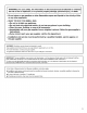
WARNING: For your safety, the information in this manual must be followed to minimize the risk of fire or explosion, or to prevent property damage, personal injury, or death. ~ Do not store or use gasoline or other flammable vapors and liquids in the vicinity of this or any other appliance. -=WHAT TO DO IF YOU SMELL GAS: + Do not try to light any appliance. + Do not touch any electrical switch; do not use any phone in your building. » Clear the room, building, or area of all occupants.
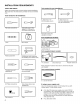
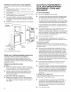
INSTALLATION REQUIREMENTS TOOLS AND PARTS Gather the required fools and parts before starting installation. Read and follow the instructions provided with any tools listed here.
Parts needed: (Not supplied with dryer) Check local codes. Check existing electrical supply and venting. See “Electrical Requirements” and “Venting Requirements” before purchasing parts. Mobile home installations require metal exhaust system hardware available for purchase from the dealer from whom you purchased your dryer. For further information, please refer to the “Assistance ar Service" section in your “Use and Care Guide.
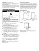
Spacing for recessed area or closet installation The dimensions shown are for the recommended spacing allowed. ®m Additional spacing should be considered for ease of installation and servicing. ®m Additional clearances might be required for wall, door, and floor moldings. ® Additional spacing all sides of the dryer is rerecorded to reduce noise transfer. ® For closet installation, with a door, minimum ventilation openings in the tap and bottom of the door are required.
If your outset looks like this: Then choose a 4-wire power supply cord with ring of spade terminals and UL listed strain relief. The 4-wire power supply cord, at least 4 fi. (1.22 m} long, must have 4 10-gauge solid copper wires and match a 4-wire receptacle of NAME Type 14-30 KR. The ground wire (ground 4-wire conductor} may be either green or bare. The receptacle neutral conductor must be identified by a (14-30) white cover.
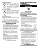
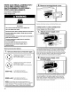
GAS DRYER POWER HOOKUP U.S.A. AND CANADA ELECTRICAL REQUIREMENTS WARNING Electrical Shock Hazard Plug into a grounded 3 prong outlet, Do not remove ground prong. Do not use an adapter. Da not use an extension cord, Failure to follow these instructions can result in death, fire, or electrical shock. ® 120 Volt, 80 Hz, AC only, 15or amp fused electrical supply Is required. A time-delay fuse or circuit breaker is corresponded. It is also recommended that a separate circuit serving only this dryer be provided.
® Lengths over 20 ft. (6.1 m) should use larger tubing and a different size adapter fitting, ® if your dryer has been converted to use LP gas, 3/8" LP compatible copper tubing can be used. if the total length of the supply fine is more than 20 ft. (6.1 m), use larger pipe. NOTE: Pipe-joint compounds that resist the action of LP gas must be used. Do not use TEFLON®! tape. wm Must include shut-off valve In the U.S.A: An individual manual shut-off valve must be installed within six {6} fi. {1.
MAKE ELECTRICAL CONNECTION U.S.A. ONLY (EFFECTUATE LE ENCOURAGEMENT ELECTRIC TEATS-UNIS SETTLEMENT) ELECTRICAL CONNECTION Power Supply Cord UX Fire Hazard Use a new UL listed 30 amp power supply cord, Use a UL listed strain relief. Disconnect power before making electrical connections. Connect neutral wire {white or center wire) to center terminal (silver). Ground wire {green or bare wire} must be connected to green ground connector, Connect remaining 2 supply wires to remaining 2 terminals (gold).
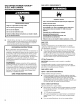
If your outlet looks like this: Power supply cord 4-wits receptacle Q (NAME Type 14-30R): “4-Wire Power Supply Cord = Connection”. Power supply cord 3-wire receptacle (NAME Type 10-30R): Go to “3-Wire Power Supply Cord Connection”. 4-wire Power Supply Cord Connection IMPORTANT: A 4-wire connection is required for mobile homes and where local codes do not permit the use of 3-wire connections. Sy & 3 4-wire receptacle (NAME type 14-3RD) 4-prong fig Spade terminals with upturned ends Ring terminals 1.
3-wire Power Supply Cord Connection Use where local codes permit connecting cabinet-ground conductor to neutral wire. (3. Connect remaining wires pe 7S) 3-wire receptacle (NAME 3-prong plug type 10-3RD} Connect remaining wires to outer terminal block screws, Tighten screws. Finally, reinsert tab of terminal block cover into slot of dryer rear panel. Secure cover with hold-down screw. Now, go to “Venting Requirements.
Direct Wire Strain Relief 1. Attach direct wire strain relief Unscrew the removable conduit connector {A} and any screws from a 3/4" (19 mm) UL listed strain relief (UL marking on strain relief). Put the threaded section of the strain relief {C} through the hole below the terminal block opening (B). Reaching inside the terminal block opening, screw the removable conduit connector (A) onto the strain relief threads. 2. Attach direct wire cable Put direct wire cable through the strain relief.
( 4. connect ground wire Conn act ground wire {green or bare) (F} of direct wire cable to external ground conductor screw (A) Tighten screw. 9 (@ li Place hooked ends of remaining direct wire cable wires under outer terminal block screws (hooks facing right). Squeeze hooked ends together and tighten screws. Finally, reinsert tab of terminal block cover into slot of dryer rear panel. Secure cover with hold-down screw. Now, go to “Venting Requirements.
Optional 3-wire Connection You must verify with a qualified electrician that this grounding method is acceptable before connecting, 1. Prepare to connect neutral ground wire and neutral wire Remove center terminal block screw (Bl. Remove neutral ground wire from external ground conductor screw (A). 2. Connect neutral ground wire and neutral wire Connect neutral ground wire (E) and neutral wire (white or center wire} {C) of power supply cord or cable under center terminal block screw (Bj. Tighten screw. 3.
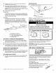
MAKE GAS CONNECTION U.S.A. AND CANADA 1. Connect gas supply to dryer Flared rae fitting Non-flared Ale fitting Remove red cap from gas pipe. Using a wrench to tighten, connect gas supply to dryer. Use pipe-joint compound on threads of all non-flared male fittings. if flexible metal tubing is used, be sure there are no kinks. NOTE: For LP gas connections, you must use pipe-joint compound resistant to action of LP gas. Do not use TEFLON® tape. C. 3/8" to 3/8" pipe elbow D.
Exhaust hoods: ® Must be at least 12" (305 mm) from ground or any object that may obstruct exhaust (such as flowers, rocks, bushes, of snow}. Recommended Styles: Box Hood Louvered Hood Acceptable Style: Angled Hood Elbows: ® 45° elbows provide better airflow than 90° elbows. Recommended Styles: Fame Good Better Clamps: ® Use clamps to seal all joints. ® Exhaust vent must not be connected or secured with screws ar either fastening devices that extend into interior of duct and catch tint.
Special provisions for mobile homes: Exhaust vent must be securely fastened to a noncombustible portion of mobile home and must not terminate beneath the mobile home. Terminate exhaust vent outside. Mobile Home Exhaust installation Determine vent path: ® Select route that will provide straightest and most direct path outdoors. ® Plan installation to use fewest number of elbows and tums. ® When using elbows or making turns, allow as much room as possible. ® Bend vent gradually to avoid kinking.
2. Attach short hose and “Y” connector Attach 2 ft {0.6 my} inlet hose to cold water faucet. Screw on coupling by hand until it is seated on faucet. Then attach “Y” connector to male end of the 2 ft (0.8 m) inlet hose. Screw on coupling by hand until it is seated on connector. Using pliers, tighten the couplings with additional two-thirds turn. NOTE: Do not over tighten, Damage to the coupling can result, Attach dryer 5 ft {1.5 my) inlet hose ends to the “Y" connector.
CONNECT VENT Using a 4° (102 mm) clamp, connect vent to exhaust outlet in dryer. if connecting to existing vent, make sure vent is clean. Dryer vent must fit over dryer exhaust outlet and inside exhaust hood, Check that vent is secured to exhaust hood with a 4" (102 mm) clamp. 2. Move dryer to final location Cer “ Move diver to final location, Avoid crushing or kinking vent. LEVEL DRYER 1. Level Dryer Place level here Place level here Check levelness of dryer from side to side. Repeat from front to back.
COMPLETE INSTALLATION CHECKLIST [1 Check that all parts are now installed. if there is an extra part, go back through steps to see what was skipped. [1 Check that you have all of your tools. {J Dispose off recycle all packaging materials. {J} Check dryer's final location. Be sure vent is not crushed ar kinked. [1 Check that dryer is level. See “Level Dryer.” {J Remove film on console and any tape remaining on dryer. Wipe dryer drum interior thoroughly with a damp cloth to remove any dust.
REVERSE DOOR SWING Tools needed: 4. Remove the 2 plastic plugs (A) located outside the dryer door opening. Flat-blade screwdriver Plastic putty knife Min. 8” long TOR T25%¢ #2 Phillips screwdriver screwdriver You can change your door swing from a right-side opening {o a left-side opening, if desired. 1. Place a towel or soft cloth on top of dryer or work space to avoid damaging the surface. Remove door from dryer cabinet 1. Open the dryer door. 5.
Remove the door assembly 3. Remove the inner door by using a plastic putty knife to separate the sides and bottom of the dryer door and trim. There are 2 snaps on left, right. and bottom of door. Insert the putty knife next to the snaps. 1. Lay the door on a flat, covered surface with the inside of the door facing up. Remove the 3 plugs with a plastic putty knife. There is a cut out to stick the putty knife under to pop out. 2. Remove the 10 screws from the dryer door and set screws off to the side, 4.
5. Remove the door strike plug with a Flathead screwdriver. 8. Lift door up and rotate trim pieces to the opposite side from Remove door strike by pinching the clips from the inside which they were removed. Then screw trim Pisces back in door panel and then rotate and push out the front. Insert door strike on the other side of dryer door by pushing in and then add the door strike plug. = 8.
10. Add inside door panel! back into the dryer door by sliding the 12. Install hinge covers and plugs. Hinge covers will go in top into the top trim piece and then lower door down. Then sideways to then rotate 90° and snap into place. press down on the corners to snap into place with the hinges fined up with the hinge holes, . Hang door by placing set pin in dryer cabinet hole and slide door down. Using a T25% screwdriver, install (A) screws and then (B) screws. Tighten all hinge screws.
SÉCURITÉ DE LA SÉCHEUSE Votre sécurité et celle des autres est trais importante. Nous donnons de nombreux messages de sécurité importants dans ce manuel et sur votre appareil ménager, Assurez-vous de toujours lire tous les messages de sécurité et de vous y conformer, Voici le symbole d'alerte de sécurité. Ce symbole d'alerte de sécurité vous signale les dangers potentiels de décès ef de blessures graves a vous eta d'autres.
AVERTISSEMENT : Pour votre sécurité, les renseignements dans ce manuel doivent être observés pour réduire au minimum les risques d’incendie ou d’explosion ou pour éviter des dommages au produit, des blessures ou un décès, Ne pas entreposer ou utiliser de Essence ou d'autres vapeurs ou liquides inflammables a proximité de cet appareil ou de tout autre appareil électroménager. ~ QUE FAIRE DANS LE CAS D'UNE ODEUR DE GAZ : + Ne pas tenter d’allumer un appareil.
EXIGENCES OUTILLAGE ET PIÈCES Rassembler las outils et pisses nécessaires avant d'entreprendre Installation. Lire et observer les instructions fournies avec chacun des outils de la liste ci-dessous.
Pièces nécessaires : (Non fourni avec la sécheuse) Consulter les codes locaux. Vérifier 'alimentation électrique et le circuit d'évacuation existants. Voir “Installations électriques” et “Exigences concernant 'évacuation” avant d'acheter les pièces. Les installations pour maison mobile nécessitent un système d'évacuation en métal disponible chez le marchand chez qui vous avez acheté votre sécheuse.
Espacement pour une installation dans un encastrement ou dans un placard Les dimensions indiquées sont pour 'espacement minimum permis. ®m Prévoir davantage d'espace pour faciliter Installation et Entretien. ®m Un espace supplémentaire peut tre requis pour les moulures de porte et de plancher et pour les plinthes. ®m Un espace supplémentaire tous les cotés de la sécheuse est recommandé pour réduire le transfert du bruit.
® Cette sécheuse est équipée d'un cordon galactique homologué par la CSA International
spécifications DE L’ALIMENTATION EN GAZ Naa ban Risque d'explosion Utiliser une canalisation neuve d'arrivée de gaz approuvée par CSA International. Installer un robinet d’arrêt, Bien serrer chaque organe de connexion de fa canalisation de gaz. En cas de connexion au gaz propane, demander a une personne qualifiée de s’assurer que la pression de gaz ne dépasse pas 330 colonne d'eau.
spécifications DU RACCORDEMENT DE L’ALIMENTATION EN GAZ ® Utiliser un coude et un adaptateur NPT de 3/8" x 3/8" entre le connecteur de gaz flexible et la conduite de gaz de la sécheuse, tel que nécessaire pour éviter le pincement. ® Utiliser uniquement un composé d'étanchéité des tuyauteries.
RACCORDEMENT AU GAZ États-Unis ET CANADA 1. Raccorder Alimentation en gaz a la sécheuse Raccord malle congrue Raccord dle non conique Retirer le capuchon rouge de la canalisation de gaz. A Aide d'une clé pour serrer, raccorder P'alimentation en gaz ala sécheuse. Utiliser un composé d'étanchéité des tuyauteries sur tous les filetages des raccords malles non coniques. Sion utilise un conduit métallique souple, veiller & ce qu'il ne soit pas pincé.
REMARQUE : Lors de l'utilisation d'un système d’évacuation existant. nettoyer et éliminer la charpie sur toute la longueur du système, et veiller 4 ce que le clapet d’évacuation ne soit pas obstrué par de la charpie. Remplacer tout conduit de plastique ou en aluminium par un conduit métallique rigide ou souple. Consulter a nouveau le tableau des systèmes d'évacuations et modifier la système d'évacuation existant au besoin pour appartenir un meilleur séchage.
Installations facultatives : YAY i Risque d’incendie Utiliser un conduit d'évacuation en métal gourd. Ne pas utiliser un conduit d’évacuation en plastique. Ne pas utiliser un conduit d'évacuation en feuille de métal. Le non-respect de ces instructions peut causer un décès ou un incendie, Si vous préférez, fa sécheuse peut &tre convertie pour évacuer par le bas et les cités. Contactez votre revendeur local pour convertir la sécheuse. A.
2. Raccordement du conduit d’évacuation au clapet Le conduit doit être placé par dessus le clapet d'évacuation. Fixer ensemble le conduit et le clapet avés une bride de 4" (102 mm}. Acheminer le conduit jusqu’a 'emplacement de la sécheuse en utilisant le chemin le plus rectiligne possible. Éviter les changements de direction & 90°. Utiliser des brides pour sceller tous les joints.
5. Fixer le long tuyau a Électrovanne de remplissage de la sécheuse et serrer les raccords = Électrovanne de remplissage 41" (15 mm) Électrovanne 4 gaz Fixer Autre extrémité du long tuyau & I'slectrovanne située au bas du panneau arriéré de la sécheuse. Visser le raccord ala main jusqu’a ce qu'il repose sur le connecteur de P'électrovanne, Terminer le serrage des raccords de deux tiers de tour supplémentaire avec une pince. REMARQUE : Ne pas serrer excessivement.
ÉTABLIR L’APLOMB DE LA SÉCHEUSE 1. Réglage de I'aplomb de la sécheuse Placer le niveau 4 cet endroit Placer le niveau a cet endroit Vérifier Aplomb de la sécheuse dans le sens transversal. Répéter opération dans le sens avant-courrière. REMARQUE : La sécheuse doit fre d'aplomb pour que le système de détection d’humidité fonctionne correctement. El) Pas d'aplomb D’APLOMB Pas d’aplomb 2.
Cette sécheuse démarre automatiquement une procédure de diagnostic au début du premier programme. Si lon revoit un code L2, ily a peut-être un problème au niveau de I'alimentation électrique du domicile empêchant élément chauffant de la sécheuse de se mettre en marche. Voir “Dépannage”. Si I'écran de circulation d'air affiche “Chuck Vent” (Vérifier le conduit d'évacuation). if est possible que le conduit d'évacuation de [a sécheuse soit écrasé ou bloqué. Voir “Dépannage”.
Inversion de la gâche 2. Retirer les 10 vis de la porte de la sécheuse at les mettre 1. Retirer a gâche de la porte (A) de Ouverture de la porte de la sécheuse. 2. Retirer la vis esthétique (B) & 'opposé de la gâche de la porte (A). » 3. Retirer la porte intérieure en séparant les cotés et fe bas de la porte de la sécheuse et de la garniture a I'aide d'un OJ couteau a mastic en plastique. 2 attaches sont situes sur fa gauche, sur la droite ef sur le bas de la porte. Insérer le A.
5. Retirer {a cheville de la gâche de la porte avec un tournevis & 8. Soulever la porte et faire pivoter les garnitures du céteau opposé tété plate. Retirer la gâche dg la porte en pignant les agrafes par rapport a leur emplacement initial. Ensuite, revisser les de Intérieur du panneau de la prote, puis en les faisant garnitures en place. pivoter af en appuyant sur "avant, Insérer fa gâche de la porte en la poussant en place de [autre cité de la porte de la sécheuse.
10. Remettre en place le panneau intérieur de la porte sur 12. Installer les couvre-chaussures et les chevilles. Les recouvrer. 1a porte en faisant coulisser le sommet sur la garniture charnières s’insèrent de coté, puis se pivotent a 80° pour supérieure, et abaisser la porte, Ensuite, embouter en s’embouter en place. appuyant sur les coins, avec les charnières alignés dans les trous de charnières. 13.