
Installation guide


15
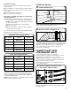
The “Vent System Charts” provide venting requirements that
will help achieve best drying performance.
Determine vent path:
■ Select route that will provide straightest and most direct
path outdoors.
■ Plan installation to use fewest number of elbows and turns.
■ When using elbows or making turns, allow as much room
as possible.
■ Bend vent gradually to avoid kinking.
■ Use as few 90° turns as possible.
Determine vent length and elbows needed for best
drying performance:
■ Use the following “Vent System Charts” to determine type
of vent material and hood combinations acceptable to use.
NOTE: Do not use vent runs longer than those specied
in “Vent System Charts.”
Exhaust systems longer than those specied will:
■ Shorten life of dryer.
■ Reduce performance, resulting in longer drying times
and increased energy usage.
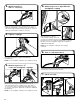
Install Vent System
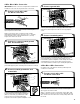
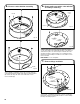
1. Install exhaust hood
12" min.
(305 mm)
12" min.
(305 mm)
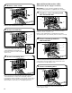
2. Connect vent to exhaust hood
Install exhaust hood and use caulking compound to seal
exterior wall opening around exhaust hood.
Vent must t over the exhaust hood. Secure vent to exhaust
hood with 4" (102 mm) clamp. Run vent to dryer location using
straightest path possible. Avoid 90° turns. Use clamps to seal
all joints. Do not use duct tape, screws, or other fastening
devices that extend into interior of vent to secure vent,
because they can catch lint.
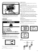
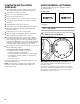
1. Turn cold water off, remove hose,
and replace rubber washer
Turn cold water faucet off and remove washer inlet hose.
Remove old rubber washer from inlet hose and replace with
new rubber washer.
CONNECT INLET HOSE
(STEAM MODEL ONLY)
For non-steam models, skip to “Connect Vent.”
The dryer must be connected to the cold water faucet using
new inlet hoses (not supplied). Do not use old hoses.
NOTE: Replace inlet hoses after 5 years of use to reduce the
risk of hose failure. Record hose installation or replacement
dates on the hoses for future reference.
Periodically inspect and replace hoses if bulges, kinks, cuts,
wear, or leaks are found.
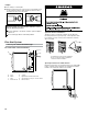
To determine if your model has a long vent system, refer to
the type code located on the serial number plate in the inner
door well. Example: An electric model would be DALV (Long
Vent) – ELE – XXXXXXX-XXX.
NOTE: For long vent systems, use of box/louvered hoods will
improve venting, regardless of length.
Long Vent System Chart
Number of
90° elbows
Type
of vent
Angled
hoods
1
4
3
2
0
Rigid metal
Rigid metal
Rigid metal
Rigid metal
Rigid metal
160 ft. (48.8 m)
150 ft. (45.7 m)
140 ft. (42.7 m)
130 ft. (39.6 m)
120 ft. (36.6 m)
Standard Vent System Chart
Number of
90° elbows
Type
of vent
Angled
hoods
1
4
3
2
0
Rigid metal
Rigid metal
Rigid metal
Rigid metal
Rigid metal
64 ft. (20 m)
54 ft. (16.5 m)
44 ft. (13.4 m)
35 ft. (10.7 m)
27 ft. (8.2 m)