
Troubleshooting guide

PAGE 5
FOR SERVICE TECHNICIAN’S USE ONLY
DO NOT REMOVE OR DESTROY
INSTALL DIAGNOSTICS
NOTE: The Service Diagnostic mode must be
activated before entering Install Diagnostics;
see procedure on page 3.
NOTE: If, at any point, the user presses the
POWER button or opens the door during Install
Diagnostics, the dryer exits to standby mode.
Active Fault Code Display
in Install Diagnostics
If the display begins flashing while in Install
Diagnostics, it is displaying an active fault
code. Active fault codes are codes that are
currently detected. Only one active fault code
can be displayed at a time.
Entry Procedure
To enter Install Diagnostics, press and release
the 2nd button used to activate the Service
Diagnostic mode. All LEDs turn off and the
START button begins to flash.
WATER-ONLY TEST: Press and hold the
START button for 5 seconds to run only the
water system test.
PERFORM ALL TESTS: Press and release the
START button to run ALL tests indicated in the
chart below.
Exit Procedure
When test is complete, press the POWER
button to exit Install Diagnostics and return
to standby mode.
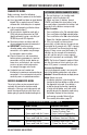
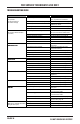
STEP TEST TEST DRYER FUNCTION COMPONENT NOTES
1 Dryer starts L2 detection algorithm. Motor On
Display shows “- - -” until voltage is
available at UI.
2
L2 detection complete. Motor On
• If Electric: Display L2 level (range 0
to 200).
• If Gas: Display “9s” for gas since L2
does not exist.
3
Dryer starts L1 detection algorithm.
Airflow detection starts at this step.
Motor On
Heater On
L2 continues to be displayed.
4
L1 detection complete.
CCU calculates L1 to L2.
Motor On
Heater On/Off
Once L1 is calculated, L1 to L2 is
immediately calculated in the CCU.
5
Press the START button to cycle
through L1, L2, and L1 to L2.
Motor On
Heater On/Off
• L1 voltage should be 120 VA C ± 10%.
• L2 voltage should be 120 VA C ± 10%,
or “9s” if gas dryer.
• L1 to L2 voltage should be 240* VAC
± 10%, or “9s” if gas dryer.
6 Airflow test near completion.
Motor On
Heater On/Off
The display will count down the final 15
seconds of the AirFlow detection routine.
7
Airflow detection complete.
Motor Off
Heater Off
When the airflow routine is complete,
the seven-segment display will show
airflow result (0=BAD, 1=GOOD,
2=INVALID).
8
Press the START button to begin
water system test.
Water Valve On
Drum Light On
Display shows “h28 ” when running.
9
Steam test running. LED drum light
and water turn on.
Water Valve On
Drum Light On
Water and LED drum light are actuated
for 30 seconds.
INSTALL DIAGNOSTICS
L
1
L
2
&
L
1
t
o
L
2
D
E
T
E
C
T
A
I
R
F
L
O
W
W
A
T
E
R
NOTE: At any time during the test, press and hold the START button for 5 seconds to jump to the water system test.
* Dryer performance is optimized for 2-phase, 240 VAC service. If complaint is regarding dryer performance and the L1 to L2 voltage
is ~208 VAC, dryer may be connected to a 3-phase service with reduced wattage that will decrease dryer performance.