
Troubleshooting guide

PAGE 9
FOR SERVICE TECHNICIAN’S USE ONLY
DO NOT REMOVE OR DESTROY
TROUBLESHOOTING TESTS
IMPORTANT: The following procedures
may require the use of needle probes
to measure voltage. Failure to use needle
probes will damage the connectors.
TEST #1: CCU Power Check
This test checks for incoming and outgoing power
to and from the Cycle Control Unit (CCU). This test
assumes that proper voltage is present at the outlet.
1. Unplug dryer or disconnect power.
2. Check for appropriate line voltages at the
outlet: 240VAC (electric 2-phase), 208VAC
(electric 3-phase), or 120VAC (gas).
If line voltage is present, go to step 3.
If line voltage is not present, check for
tripped circuit breaker or blown household
fuse. If CB (circuit breaker) is not tripped,
have customer check with qualified
electrician.
3. Remove top panel to access the machine
electronics.
4. Plug in dryer or reconnect power.
5. CCU AC – With voltmeter set to AC,
connect black probe to CCU P8-3 (N) and
red probe to P9-2 (L1). (See Figure 2.)
If 120VAC is present, go to step 6.
If 120VAC is not present, perform TEST
#2: Supply Connections, page 10.
6. CCU +5VDC – With voltmeter set to DC,
connect black probe to CCU P2-3 (ground)
and red probe to P2-1 (+5VDC).
If +5VDC is present, go to step 9.
If +5VDC is not present, go to step 7.
7. Unplug dryer or disconnect power. Unplug
P14 from the CCU. Plug in dryer or reconnect
power and repeat step 6.
If +5VDC returns, one of the thermistors
have shorted. To diagnose thermistors,
see TEST #4a, page 15.
If +5VDC is not present, go to step 8.
8. Unplug dryer or disconnect power.
Reconnect P14 to the CCU and unplug P2 from
the CCU. Plug in dryer or reconnect power and
repeat step 6. Perform voltage check inside
header P2 on CCU, between pins 1 & 3—DO
NOT SHORT PINS TOGETHER.
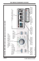
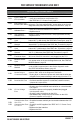
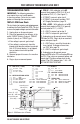
Figure 2 - CCU Connectors & Pinouts
P2 – WIDE TO UI (+5 VDC)
P2-1 BLK +5VDC
P2-2 BLU DATA
P2-3 YEL 5V GND
P8 – WATER VALVE/DOOR SWITCH
P8-5 OPEN
P8-4 TAN DOOR SWITCH
P8-3 WHT NEUTRAL
P8-2 G/Y CHASSIS GND
P8-1 RED WATER VALVE
P5 – +12VDC
P5-1
P5-2
P5-3 12V GND
P5-4
P5-5
P5-6
P5-7
P5-8 +12VDC
P9 – MOTOR/L1
P9-2 BLK L1
P9-1 LT BLU MOTOR
P13 – MOISTURE SENSOR
P13-2 RED MOISTURE SENSOR
P13-1 BLK MOISTURE SENSOR
P14 – THERMISTORS
P14-6 RED OUTLET THERMISTOR
P14-5 RED MODEL RTN (GAS MODEL)
P14-4 RED MODEL (GAS MODEL)
P14-3 RED OUTLET THERMISTOR
P14-2 RED INLET THERMISTOR
P14-1 RED INLET THERMISTOR
P13
P5
P2
P9
P14
P8
K3
K2
K1
Heater Relay #1
(Gas & Elect.)
L1 – BLK
Heater (E) – VLT
Heater (G) – RED
Heater Relay #2
(Elect. Only)
L1 – BLK
Heater – VLT
Motor Relay
•
= pin-1