
Owner's Manual
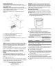


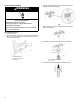


Table Of Contents
- Range Safety
- Self-Cleaning Cycle (on some models)
- General Cleaning
- Tools and Parts
- Location Requirements
- Electrical Requirements - U.S.A. Only
- Unpack Range
- Install Anti-Tip Bracket
- Adjust Leveling Legs
- Level Range
- Electrical Connection - U.S.A. Only
- Verify Anti-Tip Bracket Is Installed and Engaged
- Remove/Replace Drawer
- Oven Door
- Complete Installation

11
4-Wire Connection: Power Supply Cord
Use this method for:
� New branch-circuit installations (1996 NEC)
� Mobile homes
� Recreational vehicles
� In an area where local codes prohibit grounding through the
neutral
1. Part of metal ground strap must be cut out and removed.
A. Metal ground strap
B. Discard
C. Ground-link screw
2. Use a Phillips screwdriver to remove the ground-link screw
from the back of the range. Save the ground-link screw and
the end of the ground link under the screw.
3. Feed the power supply cord through the strain relief on the
cord/conduit plate on bottom of range. Allow enough slack to
easily attach the wiring to the terminal block.
A. Terminal block
B. Ground-link screw
C. UL listed strain relief
D. Power supply cord wires
4. Use Phillips screwdriver to connect the green ground wire
from the power supply cord to the range with the ground-link
screw. The ground wire must be attached first.
5. Use 3/8" (9.5 mm) nut driver to connect the neutral (white)
wire to the center terminal block post with one of the 10-32
hex nuts.
A. 10-32 hex nut
B. Ground-link screw
C. Line 2 (red)
D. Green ground wire
E. Neutral (center) wire
F. Line 1 (black)
6. Connect line 2 (red) and line 1 (black) wires to the outer
terminal block posts with 10-32 hex nuts.
7. Securely tighten hex nuts.
NOTE: For power supply cord replacement, use only a power
cord rated at 250 V minimum, 40 A or 50 A that is marked for
use with nominal 1
3
⁄
8
" (3.5 cm) diameter connection opening,
with ring terminals and marked for use with ranges.
8. Tighten strain relief screws.
9. Replace terminal block access cover.
3-Wire Connection: Power Supply Cord
Use this method only if local codes permit connecting chassis
ground conductor to neutral wire of power supply cord.
1. Feed the power supply cord through the strain relief in the
cord/conduit plate on bottom of range. Allow enough slack to
easily attach the wiring to the terminal block.
A. Terminal block
B. Ground-link screw
C. UL listed strain relief
D. Power supply cord wires -
large opening
2. Use 3/8" (9.5 mm) nut driver to connect the neutral (white)
wire to the center terminal block post with one of the 10-32
hex nuts.
A. 10-32 hex nut
B. Line 2 (red)
C. Ground-link screw
D. Neutral (white) wire
E. Line 1 (black)
3. Connect line 2 (red) and line 1 (black) wires to the outer
terminal block posts with 10-32 hex nuts.
4. Securely tighten hex nuts.
NOTE: For power supply cord replacement, only use a power
cord rated at 250 V minimum, 40 A or 50 A that is marked for
use with nominal 1
3
/
8
" (3.5 cm) diameter connection opening,
with ring terminals and marked for use with ranges.
5. Tighten strain relief screws.
IMPORTANT: Verify the tightness of the hex nuts.
6. Replace terminal block access cover.