
Owner's Manual


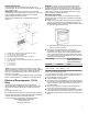


Table Of Contents
- Range Safety
- Self-Cleaning Cycle (on some models)
- General Cleaning
- Tools and Parts
- Location Requirements
- Electrical Requirements - U.S.A. Only
- Unpack Range
- Install Anti-Tip Bracket
- Adjust Leveling Legs
- Level Range
- Electrical Connection - U.S.A. Only
- Verify Anti-Tip Bracket Is Installed and Engaged
- Remove/Replace Drawer
- Oven Door
- Complete Installation

8
If connecting to a 3-wire system:
Local codes may permit the use of a UL listed, 3-wire, 250 V, 40 or
50 A range power supply cord (pigtail). This cord contains 3
copper conductors with ring terminals or open-end spade
terminals with upturned ends, terminating in a NEMA Type 10-50P
plug on the supply end. Connectors on the appliance end must be
provided at the point the power supply cord enters the appliance.
This uses a 3-wire receptacle of NEMA Type 10-50R.
3-wire receptacle (10-50R)
If connecting to a 4-wire system:
This range is manufactured with the ground connected to the
neutral by a link. The ground must be revised so the green ground
wire of the 4-wire power supply cord is connected to the cabinet.
See “Electrical Connection - U.S.A. Only” section.
Grounding through the neutral conductor is prohibited for new
branch-circuit installations (1996 NEC); mobile homes; and
recreational vehicles, or an area where local codes prohibit
grounding through the neutral conductor.
When a 4-wire receptacle of NEMA Type 14-50R is used, a
matching UL listed, 4-wire, 250 V, 40 or 50 A, range power supply
cord (pigtail) must be used. This cord contains 4 copper
conductors with ring terminals or open-end spade terminals with
upturned ends, terminating in a NEMA Type 14-50P plug on the
supply end.
The fourth (grounding) conductor must be identified by a green or
green/yellow cover and the neutral conductor by a white cover.
Cord should be Type SRD or SRDT with a UL listed strain relief
and be at least 4 ft (1.22 m) long.
4-wire receptacle (14-50R)
The minimum conductor sized for the copper 4-wire power cord
are:
40 A circuit
2 No.-8 conductors
1 No.-10 white neutral
1 No.-10 green grounding
INSTALLATION
Unpack Range
WARNING
Excessive Weight Hazard
Use two or more people to move and install or uninstall
appliance.
Failure to do so can result in back or other injury.
1. Remove shipping materials, tape and film from the range.
Keep cardboard bottom under range. Do not dispose of
anything until the installation is complete.
2. Remove oven racks and parts package from oven and
shipping materials.
3. To remove cardboard bottom, first take 4 cardboard corners
from the carton. Stack one cardboard corner on top of
another. Repeat with the other 2 corners. Place them
lengthwise on the floor behind the range to support the range
when it is laid on its back.
4. Using 2 or more people, firmly grasp the range and gently lay
it on its back on the cardboard corners.
5. Remove cardboard bottom.
The leveling legs can be adjusted while the range is on its
back. See the “Adjust Leveling Legs” section.
NOTE: To place range back up into a standing position, put a
sheet of cardboard or hardboard on the floor in front of range
to protect the flooring. Using 2 or more people, stand range
back up onto the cardboard or hardboard.
Install Anti-Tip Bracket
WARNING
Tip Over Hazard
A child or adult can tip the range and be killed.
Install anti-tip bracket to floor or wall per installation
instructions.
Slide range back so rear range foot is engaged in the
slot of the anti-tip bracket.
Re-engage anti-tip bracket if range is moved.
Do not operate range without anti-tip bracket installed
and engaged.
Failure to follow these instructions can result in death or
serious burns to children and adults.
1. Remove the anti-tip bracket from the inside of the oven.
2. Determine which mounting method to use: floor or wall.
If you have a stone or masonry floor, you can use the wall
mounting method. If you are installing the range in a mobile
home, you must secure the range to the floor.
This anti-tip bracket and screws can be used with wood or
metal studs.