RANGE SAFETY Your safety and the safety of others are very important. We have provided many important safety messages in this manual and on your appliance. Always read and obey all safety messages. This is the safety alert symbol. This symbol alerts you to potential hazards that can kill or hunt you and others. All safety messages will follow the safety alert symbol and either the word “DANGER” or “WARNING.
INSTALLATION REQUIREMENTS Took cans Posts Gather the required tools and parts before starting installation. Read and follow the instructions provided with any tools listed here. Tools Needed uw Tape measure mw Masking tape wm Flat-blade screwdriver wm 14" {6.4 mm) drive ratchet m Phillips screwdriver m5” (6.4 mm) nut driver nm Level m % (9.
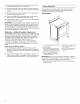
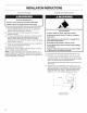
m Cabinet opening dimensions that are shown must be used. Given dimensions are minimum clearances. m The anti-tip bracket must be installed. To install the anti-tip bracket shipped with the range, see “Install Anti-Tip Bracket” section. m Grounded electrical supply is required. See the appropriate “Electrical Requirements” section, m Contact a qualified floor covering installer to check that the floor covering can withstand at least 200°F m Use an insulated pad or 15” (0.
Cabinet Dimensions Cabinet opening dimensions shown are for 25” (84.0 cm) counter top depth, 24” 61.0 cm) base cabinet depth and 36” (91.4 om) counter top height. IMPORTANT: If installing a range hood or microwave hood combination above the range. follow the range hood or microwave hood combination installation instructions for dimensional clearances above the cook top surface. Range may be installed next to combustible walls with zero clearance.
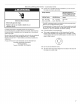
& If codes armpit and a separate ground wire is used, if is recommended that a qualified electrical installer determine that the ground path and wire litigate are in accordance with local codes. Do not use an extension cord. Be sure that the electrical connection and wire size are adequate and in conformance with the National Electrical Code. ANSI/ PAN 70-latest edition and all local codes and ordinances.
Electrical Shock Hazard Electrically ground range. Failure to do so can result in death, fire, or electrical shock. If codes armpit and a separate ground wire is used, if is recommended that a qualified electrical installer determine that the ground path is adequate and wire gauge are in accordance with local codes. Be sure that the electrical connection and wire size are adequate and in conformance with CSA Standard ©22.1, Canadian Electrical Code, Part 1 latest edition, and all local codes and ordinances.
INSTALLATION INSTRUCTIONS Sparse Unpack Be Excessive Weight Hazard Use two or more people to move and install range. Failure to do so can result in back or other injury. 1. Remove shipping materials, tape and film from the range. Keep cardboard bottom under range. Do not dispose of anything until the installation is complete. 2. Remove oven racks and parts package from oven and shipping materials. 3.
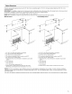
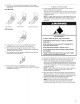
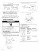
4. Drill two 18" (3 mm) holes that correspond to the bracket holes of the determined mounting method. See the following illustrations. Floor Mounting Fear position Diagonal (2 options) Wall Mounting 5. Using the two #10 x 158” {4.1 om) Phillips-head screws provided, aunt anti-tip bracket to the wall or floor. §. Move range close enough to opening to allow for final electrical connections. Remove shipping base, cardboard or hardboard from under range. 7.
1. coe oo Loved Roy Place level on the oven bottom, as indicated in one of the two figures below, depending on the size of the level. Check with the level side to side and front to back. if range is not level, use a wrench or pliers to adjust leveling fags up or down until the range is level. NOTE: Range must be level for satisfactory baking performance and best cleaning results using Lingual. iff” Self-Clean Technology. Eh nobility Echo Coreligionist 115A.
3-Wire Connection: Power Supply Cord Use this method only if local codes permit connecting chassis ground conductor to neutral wire of power supply cord. 1. Feed the power supply cord through the strain relief on the cord/conduit plate on bottom of range. Allow enough slack to easily attach the wiring to the terminal block. A. Terminal block B. Ground-link screw ©. UL sifted strain relief D. Power supply cord wires lags opening 2. Use" {1.
4. Use a Phillips screwdriver to connect the green ground wire from the power supply cord to the range with the ground-link screw and ground-link section. Tha ground wire must be attached over the ground-link section. 8. Use" {1.0 cm nut driver to connect the neutral (white) wire 10 the center terminal block post with one of the 10-32 hex nis. A, 10-32 hex nut B. Ground-link screw C. Line 2 dread) wire D. Green ground wire E Neutral (white} wire F Line 1 (black) wire &.
4. Assemble a UL listed conduit connector in the opening. 3-Wire Connection: Direct Wire Use this method only if local codes permit connecting ground conductor to neutral supply wire, 1. Pull the wires through the conduit on cord/conduit plate on A. Removable retaining nut 8B. Conduit 5. Tighten strain relief screw against the flexible conduit. Direct Wire Installation: Copper or Aluminum Wire This range may be connected directly to the fuse disconnect or circuit breaker box.
Bare Wire Torque Specifications Attaching terminal lugs to the terminal block 20 Abs-in. (2.3 N-m) 4-Wire Connection: Direct Wire Wire Awg Torque Use this method for: 8 gauge copper 25 BS-in, (2.8 N-m} New branch-circuit installations (1996 NEC) 6 gauge aluminum 35 Abs-in. (4.0 N-m) m Mobile homes 3. Use %” {1.
4. Attach terminal lugs to line 1 (black), neutral {white}, and line 2 {red) wires, Loosen (do not remove) the setscrew on the front of the terminal lug and insert exposed wire end through bot torn of terminal lugs. Securely tighten setscrew to torque as shown in the following Bare Wire Torque Specifications chart. Terminal lug B. Setscrew ©. Line 2 Fred) wire D. Neutral (white) wire E Line 1 (black) wire Bare Wire Torque Specifications Attaching terminal lugs to the terminal block 20 Abs-in. {2.
5 y Audi On Ranges Equipped with a Premium Storage Drawer: 1. Slide range into final location, making sure rear leveling leg slides into anti-tip bracket. 2. Remove the premium storage drawer. See the “Removes Replace Drawer” section, 3. Use a flashlight to look underneath the bottom of the range. 4. Visually check that the rear range foot is inserted into the slot of the anti-tip bracket, On Ranges Equipped with a Warming Drawer or Baking Drawer: 1.
St For normal range use, it is not suggested to remove the oven door. However, if removal is necessary, make sure the oven is off and cool. Then, follow these instructions. The oven door is heavy. Cr van Do Remove all items from inside the baking drawer, warming drawer ot premium storage drawer, and then allow the range to cool completely before attempting to remove the drawer. To Remove: To Remove: 1. Open oven door all the way. 1. Open the drawer to its fully open position. 2.
Check that all parts are now installed. If theta is an extra part, go back through the steps to see which step was skipped. Check that you have all of your tools. Check that you have all of the range accessories, especially vane racks. These accessories may be in the range packaging. Dispose of/recycle all packaging materials. Check that the range is level. See the “Level Range” section.
SÉCURITÉ DE LA CUISINIÈRE Votre sécurité et celle des autres est trais importante. Nous donnas de nombreux messages de sécurité importants dans ce manuel et sur votre appareil ménager. Assurez-vous de toujours lire tous les messages de sécurité et de vous y conformer.
EXIGENCES D’INSTALLATION Ondine of piques Rassembler les outils et pinces nécessaires avant d'entreprendre Piges nécessaires installation. Lire et observer les instructions fournies avec En cas d'utilisation d'un cordon d’alimentation électrique © chacun des outils de la liste ci-dessous. m Cordon d'alimentation homologation UL) conçu pour Outils nécessaires utilisation avec une cuisinière.
SH IMPORTANT : Observer les dispositions de fous les codes ef réglemente en vigueur. wm C'est a Installateur qu’incombe la responsabilité de respecter les distances de séparation spécifies sur la plagie signalétique. La plaque signalétique se trouve derrière la porte du four, dans le coin supérieur droit du châssis. m La cuisinière doit être installée & un endroit pratique dans la cuisine.
Dimensions du placard Les dimensions de ouverture entre les placards correspondent & une installation entre des placards de 25" (84,0 cm) de profondeur, avec plan de travail de 24" (61,0 cm) de profondeur et de 36" (91,4 cm) de hauteur.
Cubes Concrétion sol AVERTISSEMENT 4 SEL w En cas de doute quant a la qualité de la liaison 3 latente delà cuisinière, consulter un électricien qualifie, Puissance nominale de la Intensité nominale Relier la cuisinière 2 la terre. Le non-respect de cette instruction peut causer un décès, un incendie ou un choc électrique. cuisinière* spécifiée du cordon d’alimentation protection du circuit 120/240 volts. 120/208 volts. A Risque de choc électrique BB 2165 kW 7.82125 16,6 & 22.
INSTRUCTIONS D’INSTALLATION AVERTISSEMENT Risque du poids excessif 5 cle personnes pour déplacer et re. utiliser deux o installer la cui Le non-respect de celle instruction peut causer une blessure au dos ou d'autre blessures, ioe ta a os bile onde ), 4 1. Ôter les matériaux d'emballage, le ruban adhésif et la pellicule protectrice de la cuisinière, Garder la base de carton sous la cuisinière. Ne rien jeter avant d avoir complètement terminé installation. 2.
4. Percer deux trous de (3 mim) qui correspondent aux trous de la bride selon la méthode de montage détermine. Voir les illustrations suivantes. Montage au plancher , 7 ER Position aniridie Position avant Diagonale (2 options) Montage mural 5. Laide des deux vis a tété Phillips (4,1 cm) fournies, visser la bride basculement au mur au au plancher. 8. Rapprocher la cuisinière le plus prés possible de "ouverture afin de faciliter les raccordements électriques définitifs.
4. Lorsque la cuisinière est 4 la hauteur souhaitée, vérifier que Espace sous la cuisinière est suffisant pour loger la bride basculement. Avant de faire glisser la cuisinière a son emplacement final, vérifier quiller sera possible de faire glisser {a bride basculement sous la cuisinière et sur le pied de nivellement arriéré avant l’installation de la bride basculement. REMARQUE : En cas d'utilisation d'un jeu de garnitures, le dessus de la table de cuisson doit &tre plus haut que le plan de travail.
3. Tenter d'incliner la cuisinière vers |'avant avec précaution. En cas de résistance immédiate, cela signifie que le pied de la cuisinière est engagé dans la bride basculement. Passer 4 I'étape 8. 4. Sil'arrigre de la cuisinière se soulève de plus de 2" (1.3 cm) du plancher sans opposer de résistance, cesser cloner la cuisinière ef la reposer doucement sur le plancher. Le pied de fa cuisinière rets pas engagé dans la bride basculement.
Est pas recommandé d’enlever la porte du four pour une Remontage : utilisation normale. Toutefois, si la dépose est nécessaire, 1. Insérer les deux bras de suspension dans la porte, Vérifier s'assurer que le four est éteint et froid. Ensuite. suivre les que les encoches de charnière sont engagées dans le cadre instructions ci-dessous. La porte du four est lourde. de la porte du four. Démontage : 1. Ouvrir la porte du four complètement. 2.
Héritier que toutes les pièces sont maintenant installées. 8'l reste une place, passer en revue les différentes étapes pour découvrir laquelle aurait été oubliée. Vérifier Ja présence de tous les outils, Vérifier que tous les accessoires de la oi ere sont présents, en particulier les grilles du four. Ces accessoires peuvent se trouver dans les matériaux d'emballage de la cuisinière. Cybercriminelle tous les matériaux d’emballage. Vérifier que la cuisinière est d’aplomb.