
Owner's Manual


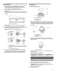

Table Of Contents
- RANGE SAFETY
- Range Safety
- RANGE MAINTENANCE AND CARE
- General Cleaning
- Self-Cleaning Cycle (on some models)
- INSTALLATION INSTRUCTIONS
- REQUIREMENTS
- Tools and Parts
- Location Requirements
- Electrical Requirements
- Gas Supply Requirements
- INSTALLATION
- Unpack Range
- Install Anti-Tip Bracket
- Adjust Leveling Legs
- Level Range
- Make Gas Connection
- Verify Anti-Tip Bracket Is Installed and Engaged
- Electronic Ignition System
- Remove/Replace Drawer
- Oven Door
- Complete Installation
- GAS CONVERSIONS
- Propane Gas Conversion
- Natural Gas Conversion
- Adjust Flame Height
- Moving the Range
- SECURITE DE LA CUISINIERE
- Securite de la cuisiniere
- ENTRETIEN ET REPARATION DE LA CUISINIERE
- Nettoyage general
- Programme d'autonettoyage (sur certains modeles)
- INSTRUCTIONS D'INSTALLATION
- EXIGENCE
- Outils et pieces
- Exigences d'emplacement
- Specifications electriques
- Specifications de l'alimentation en gaz
- INSTALLATION
- Deballage de la cuisiniere
- Installation de la bride antibasculement
- Reglage des pieds de nivellement
- Reglage de l'aplomb de la cuisiniere
- Raccordement au gaz
- Verifier que la bride antibasculement est bien installee et engagee
- Systeme d'allumage electronique
- Depose et reinstallation du tiroir
- Porte du four
- Achever l'installation
- CONVERSIONS POUR CHANGEMENT DE GAZ
- Conversion pour l'alimentation au propane
- Conversion pour l'alimentation au gaz naturel
- Reglage de la taille des flammes
- Deplacement de la cuisiniere

13
4. Remove cooktop burner caps and bases from package
containing parts. Place the burner bases as indicated by the
following illustration for your model:
For Select Models
A. Small (Auxiliary)
B. Large (Ultra
Rapid)
C. Large (Ultra Rapid)
D. Medium (Semi Rapid)
NOTE: Each round burner base is marked with one of the
following: AUX, SR, UR.
5. Align the gas tube opening in the burner base with the orifice
holder on the cooktop and the igniter electrode with the notch
in the burner base.
A. Burner cap
B. Gas tube opening
C. Burner base
D. Orifice holder
E. Igniter electrode
6. Place the burner caps on the appropriate burner bases.
IMPORTANT: The bottom of the small and medium caps are
different. Do not put the wrong size burner cap on the burner
base. Each round burner cap is marked with an AUX, SR, UR,
or ST to match with a letter on the burner base.
Small cap
(Auxiliary)
Medium cap
(Semi Rapid)
Large cap
(Ultra Rapid)
Burner caps should be level when properly positioned. If
burner caps are not properly positioned, surface burners will
not light. The burner cap should not rock or wobble when
properly aligned.
A. Incorrect
B. Correct
WARNING
Electrical Shock Hazard
Plug into a grounded 3 prong outlet.
Do not remove ground prong.
Do not use an adapter.
Do not use an extension cord.
Failure to follow these instructions can result in death,
fire, or electrical shock.
7. Plug into a grounded 3-prong outlet.
Verify Anti-Tip Bracket Is Installed
and Engaged
1. Slide range into final location, making sure rear leveling leg
slides into anti-tip bracket.
2. Remove the premium storage drawer. See the
“Remove/Replace Drawer” section.
3. Use a flashlight to look underneath the bottom of the range.
4. Visually check that the rear range foot is inserted into the slot
of the anti-tip bracket.