
Owner's Manual

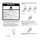

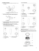
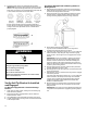
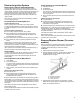
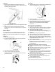
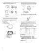
Table Of Contents
- RANGE SAFETY
- Range Safety
- RANGE MAINTENANCE AND CARE
- General Cleaning
- Clean Cycle
- INSTALLATION INSTRUCTIONS
- REQUIREMENTS
- Tools and Parts
- Location Requirements
- Electrical Requirements
- Gas Supply Requirements
- INSTALLATION
- Unpack Range
- Install Anti-Tip Bracket
- Adjust Leveling Legs
- Level Range
- Make Gas Connection
- Verify Anti-Tip Bracket Is Installed and Engaged
- Electronic Ignition System
- Remove/Replace Drawer (On some models)
- Oven Door
- Complete Installation
- GAS CONVERSIONS
- Propane Gas Conversion
- Natural Gas Conversion
- Adjust Flame Height
- Moving the Range
- SÉCURITÉ DE LA CUISINIÈRE
- Sécurité de la cuisinière
- ENTRETIEN ET RÉPARATION DE LA CUISINIÈRE
- Nettoyage général
- Programme de nettoyage
- INSTRUCTIONS D’INSTALLATION
- EXIGENCE
- Outils et pièces
- Exigences d'emplacement
- Spécifications électriques
- Spécifications de l’alimentation en gaz
- INSTALLATION
- Déballage de la cuisinière
- Installation de la bride antibasculement
- Réglage des pieds de nivellement
- Réglage de l’aplomb de la cuisinière
- Raccordement au gaz
- Vérifier que la bride antibasculement est bien installée et engagée
- Système d’allumage électronique
- Dépose et réinstallation du tiroir (Sur certains modèles)
- Porte du four
- Achever l’installation
- CONVERSIONS POUR CHANGEMENT DE GAZ
- Conversion pour l’alimentation au propane
- Conversion pour l’alimentation au gaz naturel
- Réglage de la taille des flammes
- Déplacement de la cuisinière

15
Complete Connection
1. Check that the gas pressure regulator shut-off valve is in the
“on” position.
A. Gas pressure regulator shut-off valve shown in the
“on” position
2. Open the manual shut-off valve in the gas supply line. The
valve is open when the handle is parallel to the gas pipe.
A. Closed valve
B. Open valve
3. Test all connections by brushing on an approved noncorrosive
leak-detection solution. If bubbles appear, a leak is indicated.
Correct any leak found.
4. Remove cooktop burner caps and bases from package
containing parts. Place the burner bases as indicated by the
following illustration for your model:
For models WEG745H0F and MGS8800F:
A. Small (Auxiliary)
B. Large (Ultra Rapid)
C. Oval (OV)
D. Medium (Semi Rapid)
E. Large (Ultra Rapid)
For model KSGG700E:
A. Small (Auxiliary)
B. X-Large (Stack)
C. Medium (Semi Rapid)
D. Medium (Semi Rapid)
E. Large (Ultra Rapid)
For model KSGB900E:
A. Small (Auxiliary)
B. X-Large (Stack)
C. Oval (OV)
D. Medium (Semi Rapid)
E. Large (Ultra Rapid)
NOTE: Each round burner base is marked with one of the
following: AUX, SR, UR, ST.
5. Align the gas tube opening in the burner base with the orifice
holder on the cooktop and the igniter electrode with the notch
in the burner base.
A. Burner cap
B. Gas tube opening
C. Burner base
D. Orifice holder
E. Igniter electrode